


Transreceiver plays a crucial role in CAN bus communication, transmitting data from the MCU to the CAN network. While most MCUs, such as the ESP32, have TWAI support, they still require an external CAN bus transceiver.
These transceivers can be quite expensive, so we’ll design our own CAN bus module that costs under 30 rupees and 60 rupees, including the PCB if you get it from the manufacturer in a panel. Additionally, this module is more advanced than those available in the market. It provides automatic level shifting and compatibility with both 3V and 5V logic.
Furthermore, it offers the option to make the CAN bus active or standby. The module also includes a dual connector with pin headers or FPC connectors, allowing direct connection to the board, such as the IndusBoard Coin or a direct connector using its FPC connector pin.

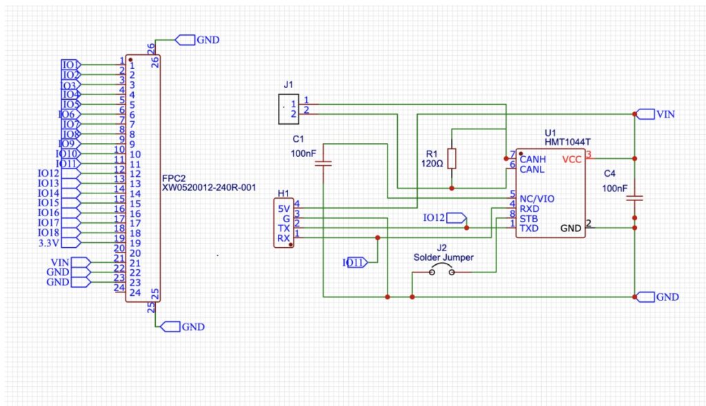
Bill of Material
CAN Bus Transceiver Design
For this design, we will use the HMT1044T IC, which provides both standby mode and active mode operation for the CAN bus using the STB pin. As per the datasheet, the chip operates over a wide voltage range from 2.2 V to 5.5 V. It also provides bus fault protection up to ±70 V, thermal-shutdown protection, and several other built-in safety features, all within a reasonable price range.
In this design, decoupling capacitors are used at the VCC and VN pins. For automatic internal level shifting, a 100 nF capacitor is connected to the VIO pin.
To configure the active and standby modes, a solder jumper is added between the STB and GND pins. If the transceiver needs to remain always active, the solder jumper can be shorted. Otherwise, a wire can be soldered to the jumper pad and controlled by the MCU, allowing the system to switch between standby and active modes, helping reduce overall power consumption.
PCB Design
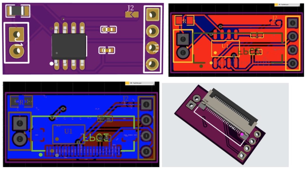
For PCB design, we’ve made it incredibly compact, allowing multiple boards to be integrated into a single panel. This significantly reduces the PCB manufacturing cost by up to ₹5–10 per PCB during panel production.
The individual components themselves cost approximately ₹20 to ₹30, resulting in a complete module that can be assembled for under ₹50–60.
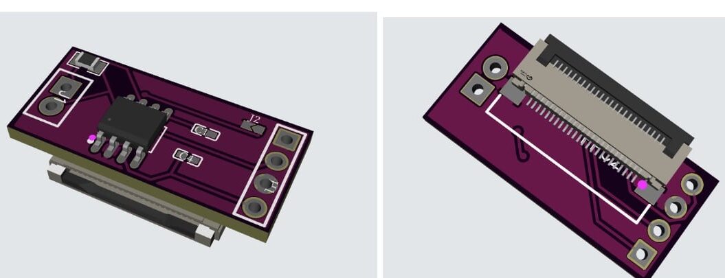
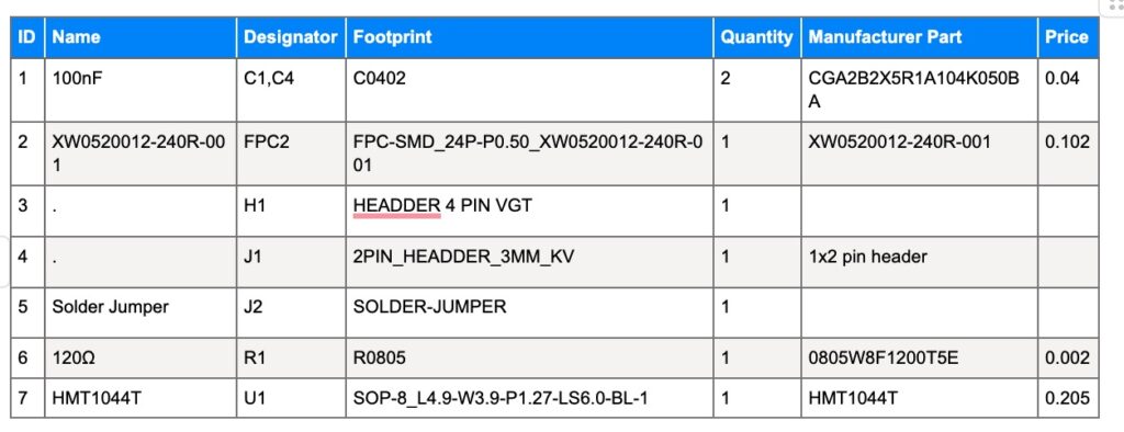
The FPC connector is mounted on the bottom layer of the PCB, while the primary components are placed on the top layer.
Additionally, a solder jumper is provided on the PCB, enabling users to select between active and standby mode settings.
More CAN Bus projects:
- CAN Bus Vehicle Sensor
- CAN Bus Controller Module
- CAN Bus To Control Appliances On Any Floor Of A Building
