If you’ve ever worked with N20 gear motors, you already know the struggle—adding an external motor driver module increases wiring, takes up space, and makes your design messy.
In this DIY project, we’ll build a super-compact H-bridge motor driver that mounts directly onto the motor itself. No extra module. No clutter.
You’ll end up with a clean, integrated motor + driver unit that gives you full control over speed and direction, while keeping the design extremely compact.

What You’ll Build:
In this project, you’ll create a tiny motor driver PCB that:
- Mounts directly on the back of an N20 motor
- Eliminates the need for external driver modules
- Supports PWM speed control
- Allows bidirectional rotation
- Includes low-power sleep mode
- Protects the circuit from voltage spikes
Think of it as turning a regular motor into a smart motor module.
Components Required (Bill of Materials)
Here’s everything you need for this build:
| ID | Name | Designator | Footprint | Quantity | Manufacturer Part |
| 1 | 100nF | C1,C2 | C0402 | 2 | CC0402KRX7R7BB104 |
| 2 | 10uF | C3 | C0603 | 1 | CL10A106MA8NRNC |
| 3 | 10uF | C5 | C0603 | 1 | CL10A106MP8NNNC |
| 4 | HD12V0L1B2LP-7B | D1 | X1-DFN1006-2_L1.0-W0.6-P0.65-BI | 1 | D12V0L1B2LP-7B |
| 5 | 2Pin Pad | IN, POWER | 2PIN PAD | 2 | |
| 6 | SolderPad | S | SOLDERPAD | 1 | SolderPad |
| 7 | DRV8212PDSGR | U1 | WSON-8_L2.0-W2.0-P0.50-TL-EP | 1 | DRV8212PDSGR |
| 8 | N20 | U3 | DC-MOTOR-GA12-N201 | 1 |
These components keep the design minimal, affordable, and easy to assemble.
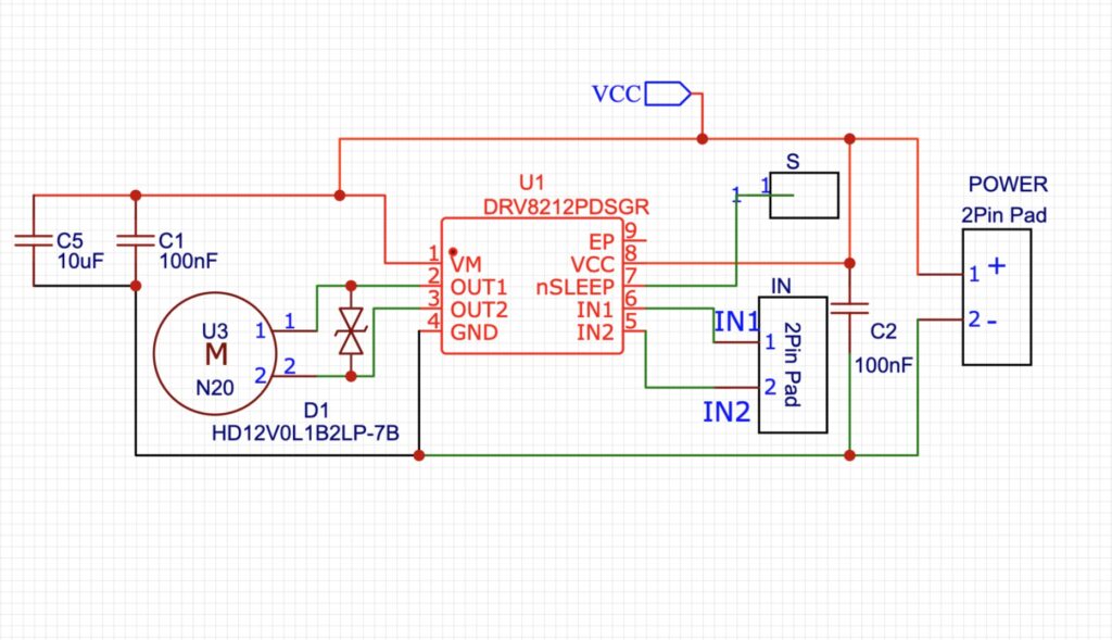
How the Circuit Works
At the core of the design is the DRV8212PDSGR, a compact H-bridge motor driver.
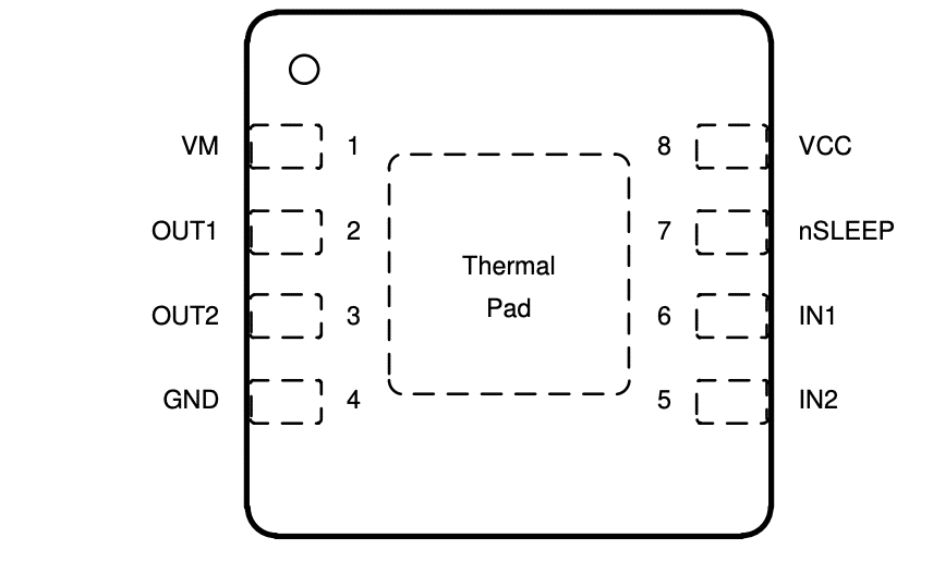
Motor Connections:
- Motor terminals → OUT1 and OUT2
- Control signals → IN1 and IN2
Control Method:
- Apply PWM signal → Controls motor speed
- Change logic levels → Controls direction
You can connect these inputs to any microcontroller, like:
- Arduino
- ESP32
- Raspberry Pi Pico
Power Handling and Stability
We’ve added a 10µF capacitor across VM and GND.
Why?
- Smooths voltage fluctuations
- Reduces electrical noise
- Supplies surge current during startup
- Keeps the motor stable under load changes
Without this, your motor may behave unpredictably.
Protecting the Circuit (TVS Diode Explained)
Motors are inductive loads, which means they generate back EMF (voltage spikes) when switching off or reversing.
Problem:
These spikes can:
- Damage the driver IC
- Destroy internal MOSFETs
- Introduce noise
Solution: TVS Diode
We’ve added a TVS diode across OUT1 and OUT2.
How it works:
- Stays inactive during normal operation
- Activates instantly during voltage spikes
- Clamps voltage to a safe level
- Protects the entire circuit
This is critical for long-term reliability.
Why We Chose DRV8212PDSGR?
This IC is perfect for compact DIY builds.
Key Features:
- Voltage range: 3.3V to 11V
- Current handling: ~400 mA
- Built-in sleep mode
- Wide temperature range: –40°C to +125°C
It’s small, efficient, and designed for battery-powered applications.
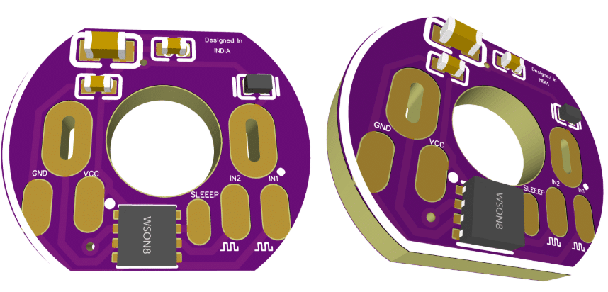
PCB Design: Making It Ultra-Compact
Here’s where the real magic happens.
Design Concept:
Instead of connecting: Motor → Wires → Driver module → MCU
We do this: Motor + Driver = Single Unit
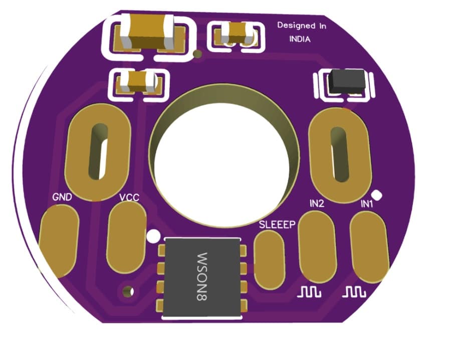
PCB Highlights:
- Matches N20 motor footprint exactly
- Mounts directly on motor terminals
- No extra wiring required
- All components placed on top layer (SMD)
This makes your project:
- Cleaner
- Smaller
- Easier to assemble
Optional Upgrade: Add Current Sensing
Want to take it further?
You can add:
- Shunt resistor
- Amplifier
This lets you:
- Monitor motor current
- Detect load conditions
- Identify stalls or overload
Not included in this design to keep it compact, but easy to add later.
Cost and Manufacturing Benefits
Because of the tiny PCB size:
- You can panelize 40+ boards in one batch
- Very low production cost
- Approx cost: ₹10–₹20 per module (excluding motor)
Perfect for:
- DIY makers
- Startups
- Mass production
Applications
This compact motor driver is ideal for:
- Robotics projects
- IoT devices
- Smart home automation
- Mini actuators
- Educational kits
- Battery-powered systems
Testing
Just mount it on the motor, connect the control signals, and you’re ready to go.
Once assembled, you’ll have:
- A fully functional motor driver
- No external module needed
- Clean and compact setup
- Reliable and protected circuit
Download PCB Design (Gerber files)