


This circuit is basically a short range, infrared remote-controlled electromagnetic relay driver. It can be used to control door motors or solenoid based locks using a compact and handy remote handset.
Electromagnetic relay circuit
The circuit comprises the IR transmitter and the receiver cum relay driver circuits. Fig. 1 shows the tiny transmitter circuit that works off a 6V (2x3V) battery. Two CR2032 Lithium button cells serve the purpose here. Push-to-on switch S1 is the trigger key. Resistor R1 and zener diode ZD1 form the traditional shunt regulator circuit. Resistor R3 limits the operating current of response indicator LED1.
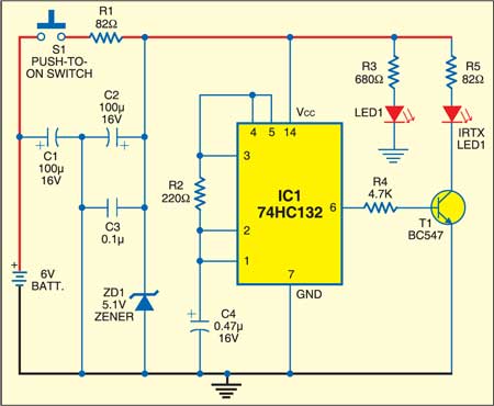
Two of the four gates of IC1 are used here. The first gate (with pins 1 and 2 as inputs and pin 3 as output) is a 10kHz oscillator. Timing components R2 and C4 determine the frequency of oscillations. The second gate (with pins 4 and 5 as inputs and pin 6 as output) is used as a buffer. The 10kHz signal for the infrared is produced by this oscillator built around the first gate. Transistor T1 is the IR transmitting LED1 driver and resistor R5 limits the current through the infrared LED. Any general-purpose IR-transmitting LED can be used here. After construction, enclose the circuit in a keychain type plastic cabinet.

Fig. 2 shows the IR receiver-cum-relay driver circuit. It works off 6V regulated power supply. Use a suitable AC mains adapter (max. 500 mA at 6V) for powering this unit.
Circuit operation
When the IR signal is received, photo-transistor T2 conducts briefly at 10kHz rate and a pulse train with 10kHz frequency appears across resistor R6. This signal is fed to the input terminal (pin 3) of PLL chip LM567 (IC2) through capacitor C5. When the amplitude and frequency of the input signal are within the capture range of the PLL decoder, its output pin 8 goes low. Resistor R8 limits the sinking current.
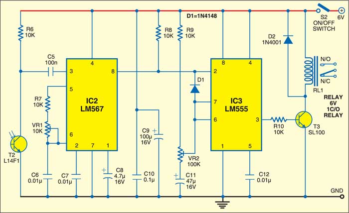
As a result, the monostable built around the timer chip (IC3) is triggered and relay RL1 energises for a finite time (1 to 5 seconds) determined by VR2 setting. The relay contacts allow switching of the door motor/lock solenoid.
The initial setting is to be done as follows: Push switch S2 of the IR receiver circuit to ‘on’ state and activate the transmitter. Now slowly vary preset VR1 until relay RL1 energises. Lock preset VR1 in this position by applying some sealant such as wax. Now connect the door motor/lock solenoid to the relay contacts with proper power supply.
The circuit has been designed to work over a very short range (max. 10 cm) to prevent its misuse.
The article was first published in December 2006 and has recently been updated.
