


Precision in human-robot interaction depends on the ability to recognise and track human faces along with detailed facial landmarks. This capability underpins emotional analysis and the development of machine learning models grounded in real human behaviour. By analysing facial features, robots can interpret responses and communicate more naturally.
Face tracking further enables real-time interaction and coordinated movement. However, accurately detecting and tracking multiple facial landmarks for expression and emotion analysis remains a challenge. Advanced robotic systems must monitor over 100 facial points in real time and respond accordingly—for example, by synchronising head movements with the user and maintaining natural eye contact.
POC Video Tutorial
This system addresses the challenge using the MediaPipe algorithm for real-time face landmark detection and tracking. Detected facial points can be recorded for analysis and for training machine learning models. The code runs across multiple platforms, including PCs, Nvidia Jetson, and Raspberry Pi, supporting face tracking, landmark analysis, and precise head and eye movement based on detected facial data.

An earlier version of this system focused on face recognition but lacked continuous face tracking and object-tracking capabilities. It can be accessed here for reference: https://www.electronicsforu.com/electronics-projects/smart-robot-face-recognition
MediaPipe can also detect and track common objects such as phones, bottles, and cups in real time. The robot can move its eyes and head to follow these objects while interacting with both people and its surroundings.
This capability enables the development of task-oriented robots that can perform activities such as picking, sorting, delivering, or handing over objects. By combining facial landmark tracking with object detection, the robot becomes more aware and responsive. It can also collect data on human-object interactions to train machine learning models for grasping, manipulation, and autonomous decision-making.
The lightweight MediaPipe framework allows the system to run efficiently on edge platforms such as Raspberry Pi, Nvidia Jetson, and standard PCs. Fig. 1 shows the author’s prototype robot tracking a face in real time while detecting facial landmark points. Components required to build the system are listed in the Bill of Materials table.
| Bill of Materials | ||
| Name | Description | Quantity |
| 3D printed parts of a robot | 3D parts of the inMoover robot face | 1 |
| Servo motor | For eye movement and head movement: 2 micro geared, 2 metallic geared MG995 or similar | 4 |
| Raspberry Pi/Nvidia Jetson/Nvidia Orion | SBC for AI image processing and control | 1 |
| 2A, 5V DC power supply | For robot and servo motor power | 1 |
| Raspberry Pi camera | 5MP or 10MP CSI camera | 1 |
Robot design and assembly: Robot face
In this design, a Raspberry Pi 4 with 2GB RAM serves as the main controller. Nvidia Jetson and Orin boards can also be connected and are recommended for improved performance. The robot’s face is based on the open source InMoov robot design. Most components are 3D-printed, along with custom mounts for the camera and Raspberry Pi. Additional single-board controllers are installed inside the head to control servos and internal mechanisms.
First, assemble the 3D-printed parts of the robot’s head. Then install the servos to enable eye and head movement. Refer to the assembly instructions here: https://inmoov.fr/eye-mechanism
Refer to Fig. 2 for guidance. After this step, proceed with assembling the eyes.
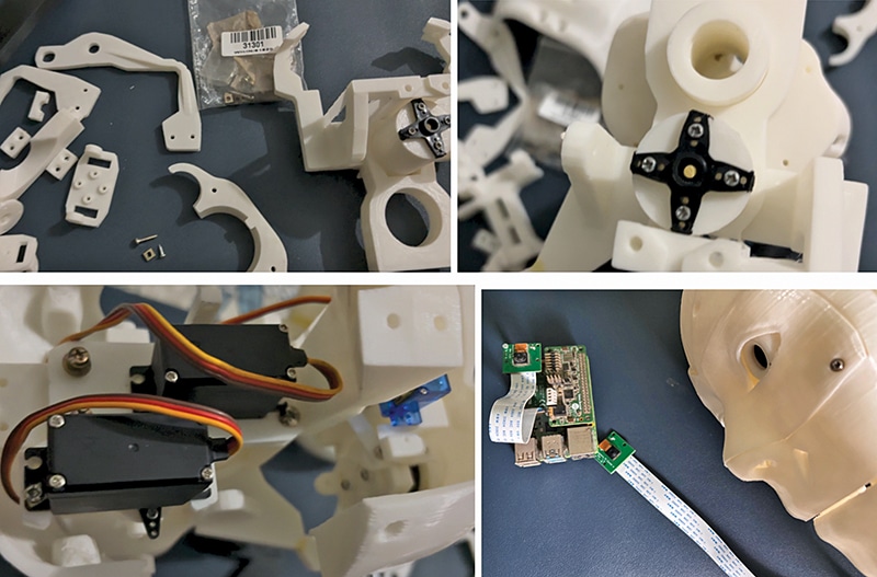
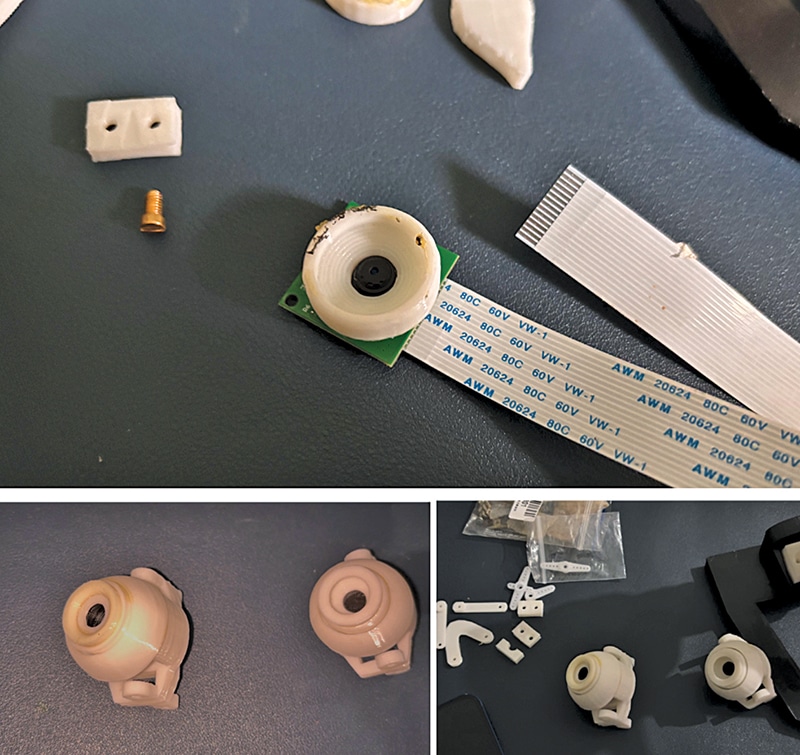
Adding camera
Place the camera inside the 3D-printed eye housing so that the robot can capture visual input. Fix the camera on one side and assemble the remaining eye components. Finally, mount the assembled eyes onto the servo-driven mechanism in the robot’s head. Refer to Fig. 3.
You can check our other facial recognition and tracking projects:
- IoT Face Recognition AI Robot
- Real-Time Face Recognition Using Python And OpenCV
- Face Following Smart Camera for Video Shooting
- Face Tracking and Movement Following Drone
Adding computing
Next, install the robot’s computing unit, which performs processing tasks, runs AI-based image processing, and supports machine learning models. Fig. 4 shows this setup.
