


 A simple Pre-Primary Tutor for kids is presented here. An Arduino board (or its equivalent Freeduino), three tactile switches and a 16×2 LCD module are the main components used here.
Arduino is selected because it is an open-source prototyping electronics platform based on flexible, easy-to-use hardware and software. It is intended for designing creative applications by hobbyists, artists and engineers.

Circuit and working
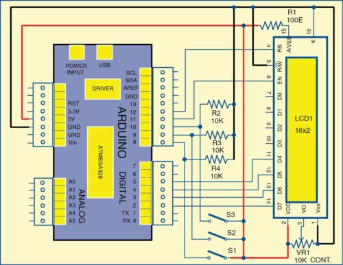
The circuit diagram of the pre-primary tutor for kids is shown in Fig. 1. ATmega8 based board is used in this design.
Software is written in Arduino programming language, which is similar to C language. Software is written and compiled using open source Arduino integrated development environment (IDE). It can be downloaded from arduino.cc. Language structure, description and library functions are also given at arduino.cc. The compiled code is also uploaded on Arduino through Arduino IDE.
Switches S1, S2 and S3 are connected to digital pins 8, 9 and 10 of Arduino, respectively. These digital pins are programmed as input pins in set-up function of sketch. Programs written for Arduino are called sketches. The set-up function in sketch is used to set up pin modes, serial ports, etc. The actual functional code will be in the loop function of sketch.
When a switch is in open condition, the corresponding digital pin is connected to ground through pull-down resistors of value 10-kilo-ohm each. When a switch is pressed, the corresponding digital pin is connected to 5V taken from Arduino. The switch-pressed states are read by digital read functions in the loop function of sketch.
The corresponding LCD display logic is also implemented in the loop function of sketch. Since switches S1 through S3 are tactile switches, contacts bounce during closure and release can cause false count. This problem is taken care of in the program by reading and comparing switch-closed conditions with a delay of 10ms.
Construction and testing
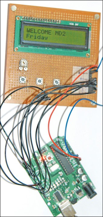
The circuit is wired on a general-purpose PCB. The prototype is shown in Fig. 2.
A USB A-B cable is used to upload the compiled sketch from the PC through Arduino IDE.
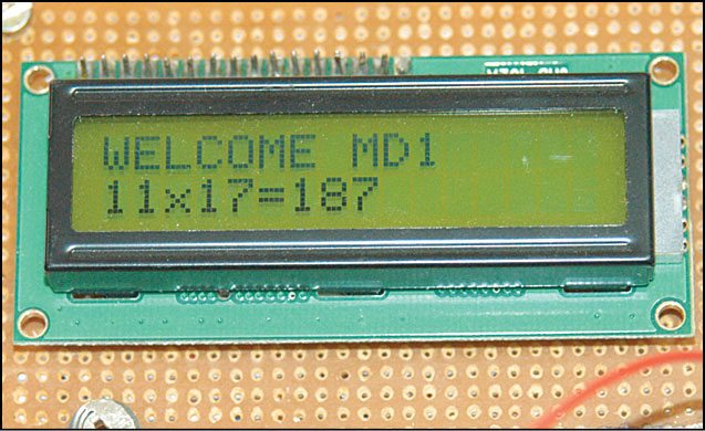
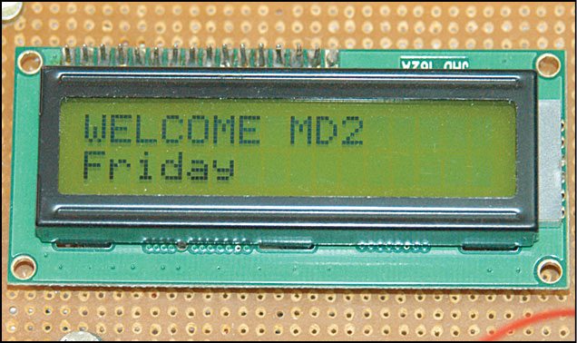
Photographs of some functions displayed on the LCD are shown in Fig. 3 and Fig. 4.
Download source code: click here
The operation is as follows:
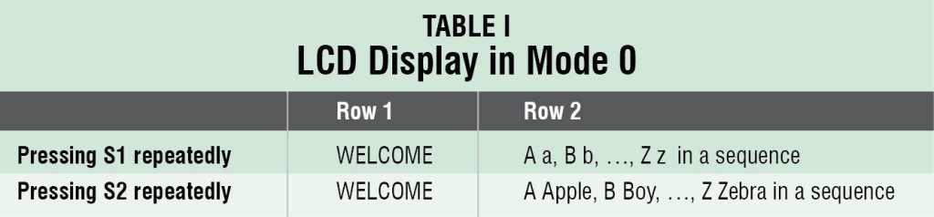
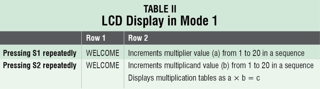
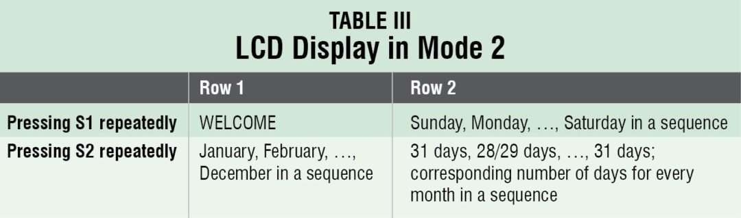
Press switch S3 repeatedly to change mode from 0, 1 and 2. Then, press S2 or S1 to change contents of the LCD.
The various functions of switches and messages displayed on the LCD are listed in Table I through Table III. For example, in mode 0, if you press switch S1 momentarily, Welcome will be displayed in the first line (row 1) of the LCD. At the same time, A a will be displayed in the second line (row 2) of the LCD. If you press S1 again, Welcome in the first row and B b will be displayed in the second row of the LCD. If you press switch S2, Welcome in the first row and A Apple will be displayed in the second row of the LCD.
VR1 preset can be used to adjust the contrast of the LCD.
Check the latest Arduino projects.
K. Sitarama Rao is M.Tech (control and instrumentation) from IIT Delhi. He is scientist G at Research Centre Imarat, DRDO, Hyderabad. He has been working in the field of missile quality and reliability for the last 15 years. He received Dr Lal C. Verman award on quality and reliability from IETE in 2010