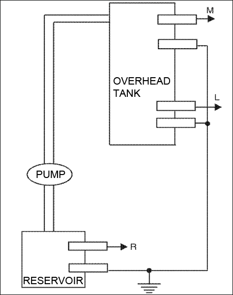
This automatic pump controller eliminates the need for any manual switching of pumps installed for the purpose of pumping water from a reservoir to an overhead tank (refer Fig.1). It automatically switches on the pump when the water level in the tank falls below a certain low-level (L), provided the water level in the reservoir is above a certain level (R). Subsequently, as the water level in the tank rises to an upper level (M), the pump is switched off automatically. The pump is turned on again only when the water level again falls below level L in the tank, provided the level in the reservoir is above R. This automated action continues.

Pump Controller Circuit
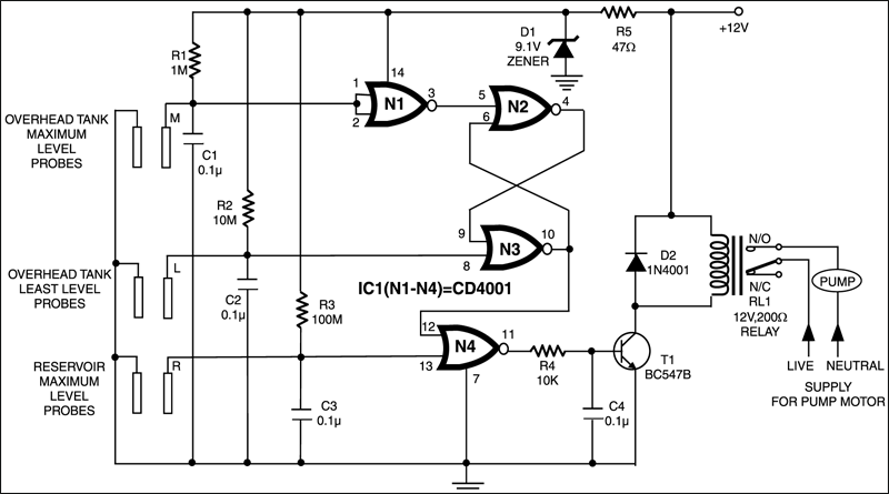
The circuit is designed to ‘overlook’ the transient oscillations of the water level which would otherwise cause the logic to change its state rapidly and unnecessarily. The circuit uses a single CMOS chip (CD4001) for logic processing.
No use of any moving electro-mechanical parts in the water-level sensor has been made. This ensures quick response, no wear and tear, and no mechanical failures. The circuit diagram is shown in Fig.2. The device performed satisfactorily on a test run in conjunction with a 0.5 HP motor and pump.

The sensors used in the circuit can be any two conducting probes, preferably resistant to electrolytic corrosion. For instance, in the simplest case, a properly sealed audio jack can be used to work as the sensor.
The circuit can also be used as a constant fluid level maintainer. For this purpose the probes M and L are brought very close to each other to ensure that the fluid level is maintained within the M and L levels.
The advantage of this system is that it can be used in tanks/reservoirs of any capacity whatsoever. However, the circuit cannot be used for purely non-conducting fluids. For non-conducting fluids, some modifications need to be made in the fluid level sensors. The circuit can however be kept intact.
The article was first published in August 1998 and has recently been updated.


