


 You will find in this article projects for interfacing an 8×8 and a 5×7 dot-matrix display with Raspberry Pi.
Since Raspberry Pi does not have enough GPIOs, we have used its I2C bus to connect to MCP23017 IO expander to have 16 additional GPIOs for connecting to LED dot-matrix display such as 8×8 or 5×7. Pin 3 (SDA) and pin 5 (SCL) are I2C pins on Raspberry Pi board. Some libraries in the form of a GPL Python script, taken from Adfruit.com, are used in this project to manage the extended GPIOs.
First, you will see how a single 8×8 LED matrix is interfaced with GPIOs through MCP23017. Then you can expand the project to interface more dot-matrix displays.

System set up
To use I2C on Raspberry Pi, you need to enable a few things in Raspbian Wheezy operating system as these are not enabled by default. This is a fairly easy process. First you edit the modules file using the command:
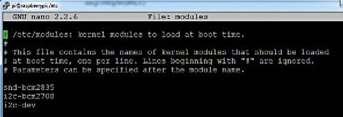
$ sudo nano /etc/modules
and add the following two lines (also refer to Fig. 1):
i2c-bcm2708
i2c-dev
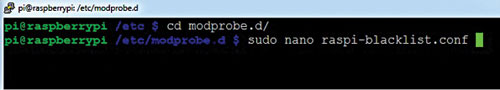
Save the file and exit nano. Next, open the raspi-blacklist.conf file by writing the command (also refer Fig. 2):
$ sudo nano /etc/modprobe.d/
raspi-blacklist.conf
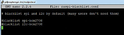
Comment out the code by putting # symbol at the beginning of the two lines as given below (also refer Fig. 3) and then save and exit.
#blacklist spi-bcm2708
#blacklist i2c-bcm2708
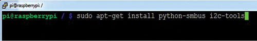
Now install the necessary software to manipulate the I2C bus using following commands (also refer Fig. 4):
$ sudo apt-get update
$ sudo apt-get install python-smbus
i2c-tools
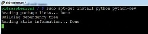
Once the software is installed, reboot your Raspberry Pi so that these effects take place permanently. Also install Python and python-dev on Raspberry Pi using following commands (also refer Fig. 5):
$ sudo apt-get install
python python-dev
For interacting with the GPIO through Python, you have to install the GPIO Python libraries. The latest library available is RPi.GPIO-0.5.5.tar.gz. Download the same from the link below:
http://raspberry-gpio-python.googlecode.com/files/
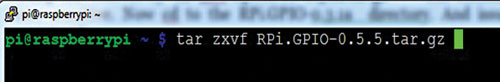
Unzip or extract the tar file by using command (also refer Fig. 6):
tar zxvf RPi.GPIO-
0.5.5.tar.gz
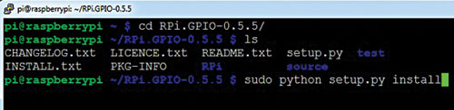
Now change directory to the RPi.GPIO-0.5.5 and write the following command (also refer Fig. 7):
$ sudo python setup.py
install
The command will install Raspberry Pi GPIO library into Python. Now reboot the Raspberry Pi using command:
$ sudo reboot
Project 1: Multiplexing of 8×8 dot-matrix display
In this project, you will use two separate files—one to create a template of figures on the 8×8 dot- matrix (using ‘1’s) and the other to control the GPIOs for drawing figures on the LED matrix. So whatever letter or character you want to display, make the changes in letter.py code and the same will be drawn on the LED matrix.
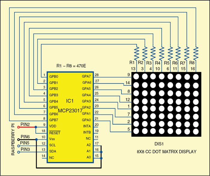
Make the connections as per the circuit shown in Fig. 9. MCP23017 (28-pin DIP) is used here as it has 16 GPIOs—8 for rows and 8 for columns of 8×8 LED matrix. Remember to use current-limiting resistors, whose values can be between 470 ohms and 1-kilo-ohm, in series with the LEDs.
Four wires are connected to the Raspberry Pi—two for I2C and two for 5V supply and ground connections.
Before testing, make sure that 5V supply is going to the correct pin in Raspberry Pi board, else it will heat up the microprocessor and damage it. Also ensure the reset pin 18 of MCP23017 is connected with +5V rail.
Circuit and working
To test the I2C connection on Raspberry Pi, open the terminal and issue the following command:
$ sudo i2cdetect -y 0
or
$ sudo i2cdetect -y 1
If your Raspberry Pi is version 1 then use 0, else 1, and watch the screen shown in Fig. 10 appear at the terminal prompt.
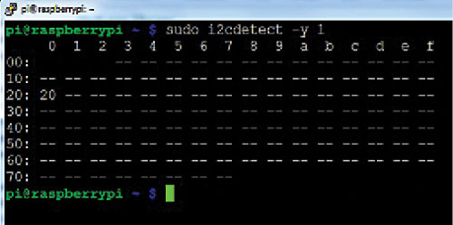
Congratulations! Your Raspberry Pi has successfully detected the hardware at 0x20 address. The address is 0×20 because all the three address pins (A0, A1, A2) of MCP23017 are set low. If you had set only A0 high (connected to +5V) the address would have become 0×21.
This signifies one fundamental issue with I2C communications: You can connect any number of devices on the I2C bus (pin 3 and pin 5) but all devices should have unique addresses. So, setting A0, A1 and A2 pins will define different addresses for different devices. You can also control the device by issuing appropriate command. You may try this as explained below to gain more confidence.
There is another way of testing the I2C connection on Raspberry Pi. Connect an LED on A0 pin and issue the following commands:
$ sudo i2cset 0x20 0x00 0x00 # this
will switch on the LED on A0
$ sudo i2cset 0x20 0x00 0x01 # this
will switch off the LED on A0
The command line program is easy, provided you understand the binary and hex conversion. Adafruit.com has an excellent library using which we can manipulate these GPIOs in a far more lucid way. The files include Adafruit_I2C.py, Adafruit_MCP230xx.py, letter.py and mcplight9.py
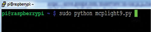
Now open the terminal and write the command given below (also refer Fig. 11):
$ sudo python mcplight9.py
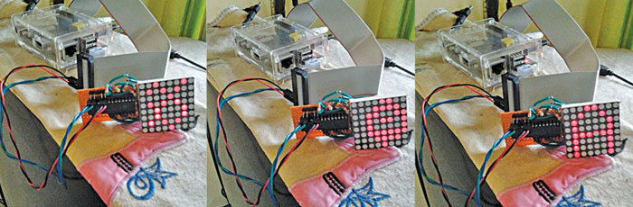
Now you will see different characters visible on your dot-matrix display as shown in Fig. 8. Each character will be displayed on the LED matrix one after another.
Project 2: Multiplexing of 5×7 dot-matrix display
Similarly, by using Adafruit libraries, as you did in the first project, you can do the multiplexing of 5X7 dot-matrix display. The libraries include Adafruit_I2C.py, Adafruit_MCP230xx.py, efy.py and mcplight9.py.
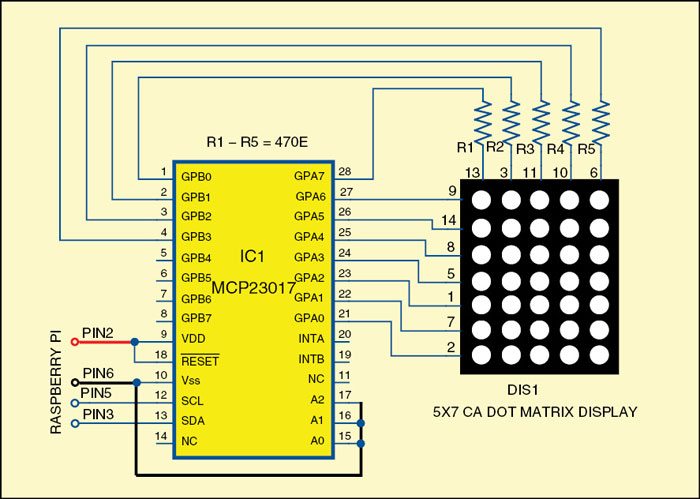
First make the connections as shown in Fig. 12. Then open the nano editor by writing the command:
$sudo nano efy.py
Now write the efy.py code. This python script will create the word EFY on the 5×7 LED matrix. Save and exit the nano editor.
Now run the code by using the command:
$sudo python efy.py
It will display E, F and Y characters sequentially, one by one, on the 5×7 dot-matrix display.
Download source code: click here
The author is an avid user of open source software. Professionally, he is a thermal power expert working as an additional general manager at NTPC Limited
