
A human detection system was designed earlier to utilise the microwave Doppler effect to detect human movement and trigger AC appliances such as light bulbs and other electrical loads up to 1A. The design incorporated a solder jumper pad for mode selection, enabling the same PCB to be configured for IoT compatibility by integrating IoT functionality into the radar switch. This configuration supports real-time radar data monitoring, alert reception, and wireless control of lights over a Wi-Fi network.
POC Video Tutorial
Coverage of the IoT code and app development for this system was planned in the previous month. Building on the existing architecture, the software and circuitry required to connect the human radar design to IoT and IIoT dashboards and user interfaces have now been created. On the hardware side, the PCB layout remains essentially unchanged, as the solder pad and FPC connector are already integrated, allowing seamless connection to any IoT board or dedicated industrial interface board.
During earlier testing, it was observed that specific microwave Doppler radar modules available on the market provide insufficient output current to trigger the optotriac in some cases, resulting in difficulty for the optocouplers when switching an AC bulb. To address this behaviour, a solder jumper was included to allow connection to a development board, enabling radar data processing and reliable bulb activation through the board. A buffer circuit or transistor may also be added if such issues arise with a specific radar module.

In most cases, the radar module can directly trigger the VO2223A, as the internal LED requires only a minimal current to activate. The LED forward voltage at 10 mA is typically 1.3-1.4V, allowing the radar module’s OUT pin to provide the necessary LED drive current.
| Bill Of Materials | |||||||
| Name | Designator | Footprint | Quantity | Manuf. Part | Manufacturer | Indian Substitute | Indian Manufacturer |
| RCWL-0516 microwave radar module | U1 | RCWL-0516 | 1 | RCWL-0516 | NA | NA | |
| LDR | U2 | UNIVIBE LAMP-LDR ARRANGEMENT_LDR3 | 1 | NA | NA | ||
| IndusBoard | U3 | FPC24 0.5mm | 1 | Coin V2 | NA | IndusBoard Coinv2 | NA |
| 100nF | C3 | C1206 | 1 | CC1206KKX7RYBB104 | YAGEO | 1206B104K251CT | Walsin |
| DB301V-3.5-2P-GN | CON1, CON2 | CONN-TH_DB301V-3.5-2P-GN | 2 | DB301V-3.5-2P-GN-S | DORABO | TL001R-3.5-2P | Connectwell |
| FPC Connector | FPC1 | OV2640 FPC 24P | 1 | AFC01-S24FCA-00 | JUSHUO | ZF5S-24-01-T-WT | Samtec Electronics India |
| VO2223A X007T | IC1 | DIP-8_7P-L9.7-W6.4-P2.54-LS7.6-BL-PE7 | 1 | VO2223A-X007T | VISHAY | VO2223A-X007T | VISHAY |
| 120Ω | R1 | R0603 | 1 | 0603WAF1200T5E | UNI-ROYAL | CRCW0603120RFKEA | VISHAY |
| 100Ω | R3 | RES-SMD_L6.4-W3.2-R2512 | 1 | SR2512FK-7W100RL | YAGEO | 100Ω SMD resistor | HTR-INDIA, Watts Electronics, Kusum/ KOHM |
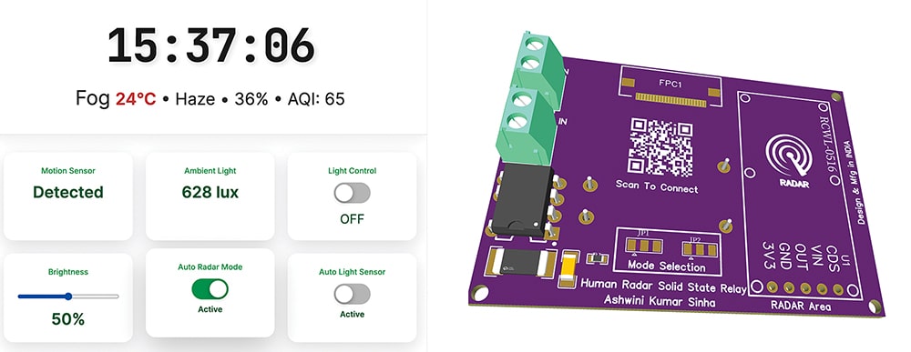
For enhanced reliability and compatibility with all RCWL microwave radar modules on the market, a buffer transistor circuit is recommended when direct triggering is not feasible. In this system, the radar output is connected directly to the development board, as testing confirmed reliable performance without a transistor buffer. Fig. 1 illustrates the radar UI dashboard and the radar PCB design.
The system supports the Made-in-India concept, incorporating nearly 80 per cent Indian components. The development board, optocouplers, and other discrete components are manufactured and designed in India. The Bill of Materials table lists all components required to build the system.
Circuit Diagram
Fig. 2 shows the circuit diagram of the system. It is built around the radar module RCWL0516 (U1), LDR (U2), IndusBoard (U3), VO2223AX007T (IC1), FPC connector (FPC1), and a few other components.
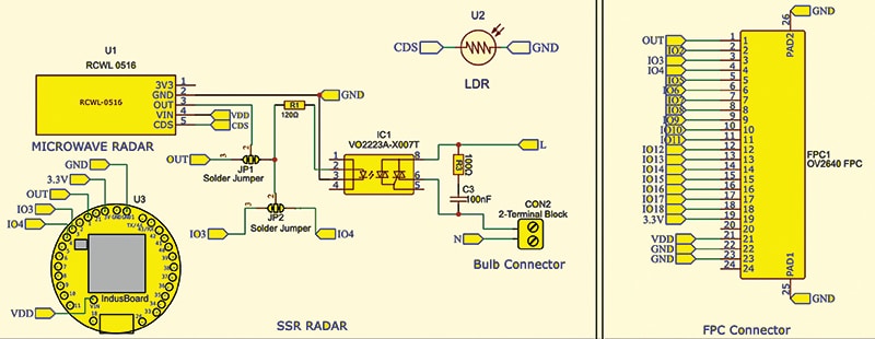
The radar module’s output is connected to IO pin-1 on the board via a solder jumper. The optocoupler input pin is connected via a solder jumper to IO pin-3 for control and to pin-4 to read the light’s on/off state. The entire DC section is powered by a 3.3V AC-DC converter module that drives the DC circuitry.
The RCWL-0516 microwave radar module receives power from the 3.3V and GND pins on the board, while its OUT pin is routed via a solder jumper (JP1) for signal selection. This jumper routes the radar’s detection signal directly to a selected I/O pin of the IndusBoard controller for processing. The unused pins VIN and CDS remain open in this configuration, as they are not required for the current design.
The radar detection signal can optionally drive the solid-state relay optocoupler (VO2223A) via a current-limiting resistor (R1). When activated, the optocoupler triggers its internal triac, enabling AC load switching. A snubber network consisting of resistor R3 and capacitor C3 is connected across the triac terminals to ensure reliable operation and protect the device from voltage spikes caused by inductive loads.
A 2-terminal connector is provided for attaching the AC bulb. The live wire (L) passes through the optocoupler output, while the neutral wire (N) connects directly to the bulb. Additional flexibility is provided through a second jumper (JP2), which enables the microcontroller to control the relay output or monitor the AC load state through another IO pin. The FPC connector accommodates an OV2640 camera module, providing scope for future feature expansion and enhanced system capability.
Code for Human Detection and Weather Monitoring
The code is written using the Arduino IDE, and the ESP32 board package must be installed first. The program includes an additional configuration section that enables the device to operate in STA mode, AP mode, or both simultaneously. This behaviour is selected in the code by assigning 0 to STA mode, 1 to AP mode, and 2 to dual-mode operation, as shown in Fig. 3.
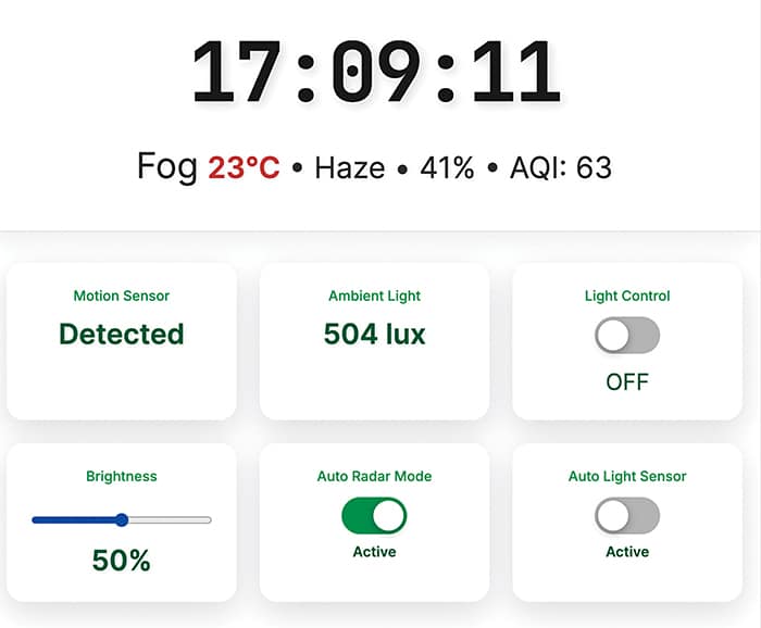
A user interface (UI) is created to control and interact with the device. The UI also includes a feature that automatically synchronises and retrieves real-time data, such as time, AQI (air quality index), and weather conditions, when connected to Wi-Fi with internet access. Fig. 3 illustrates the structure of the web dashboard UI.
Through these functionalities, the device also operates as an IoT dashboard or smart clock, providing remote control access, live time, AQI readings, and weather updates through a single interface.
In the code, the Wi-Fi SSID for the required network is configured first. The mode is then configured to operate the device as AP or STA. The current implementation enables both, although this consumes more current and power. A function is created to check the radar sensor data in real time and update it on the cards. The light sensor integrated inside the coin board is also monitored.
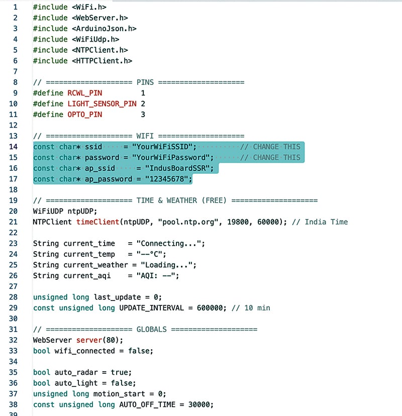
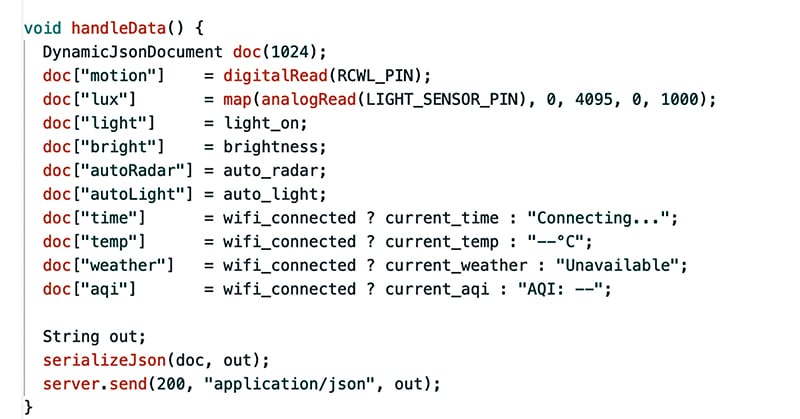
The UI supports manual or automatic light control, with options for ambient light or radar input. Fig. 4 shows the code snippet used to configure AP and STA, SSID, and password. Fig. 5 shows the data-handling function.
Construction and Testing
After uploading the source code to the development board, assembly of the radar-based SSR (solid-state relay) unit can begin as per the schematic. The RCWL-0516 microwave radar module is mounted securely, and its output pin is connected either directly to the controller’s IO pin or through the optocoupler path using the solder-jumper selection.
The VO2223 solid-state relay IC is then placed, followed by connection of the series resistor and snubber capacitor, as shown in Fig. 2, to ensure smooth AC load triggering. The 2-terminal block for the bulb or AC appliance is attached, guaranteeing correct routing of the Live (L) and Neutral (N) wires. If included in the design, the FPC camera interface is connected through the dedicated connector to provide additional sensing capability.
Once wiring is completed, the board is powered through the VIN terminal, and initial testing is performed to validate detection, triggering, and load-switching functions.
After powering the device, connect the bulb to the AC Load Terminal block, then connect the device to Wi-Fi. On a phone, the user can open Wi-Fi settings, locate the device network, and connect to it using the SSID and password configured earlier.
A browser is then opened, and the device IP address is entered. The web UI appears, providing configuration and monitoring options. The system can function as a human-motion alert device, with radar data displayed in the first card and light-sensor data in the next. The toggle button allows manual light control. If automatic switching based on radar data is required, select the radar auto mode. If automatic switching based on ambient light is preferred, select the auto-on light option.