
You can read the part 2 of this article here
The aim of the experiments under the article in three parts is to arouse the interest of learners to learn IC 555 through various experiments. Most important is that the working of each experiment is explained logically to know how the final result is achieved. The experiments are deliberately made a bit complicated in a few places as the aim is to use the internal components of the IC in different ways to create interesting situations so that the learning becomes an enjoyable experience. At the same time care is also taken to use the minimum number of components easily available. Since the experiments are performed on a breadboard, the same components can be reused for other experiments. All the experiments are performed on a 9 VDC battery. Experiment 13 has three parts: A, B and C. They use no external resistance. Every experiment in the article is distinctly different and interesting.
Experiment 13 (A)
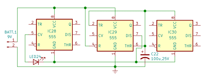
In this experiment, out of three, only one IC is powered. Apart from LED24, only one external component is used. IC29 is wired as an astable multivibrator. Only the internal 5K series resistances between pin 1 and pin 8 of IC28 and IC30 are used here to charge and discharge capacitor C22. Hence there is no need to power both the ICs. Instead of output pin 3 of IC29, pin 7 is used to show the output. Internal 5K resistance between pin 8 and pin 5 of IC28 is used as a current limiter to LED 24. On powering the circuit, the LED goes on and off in synchronous with the astable operation of IC29.
Experiment 13 (B)
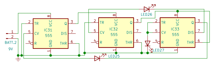
In this experiment, there are three ICs and three LEDs only. Here all three ICs are powered. No external component is used. The current limitation to each LED is also provided by an internal resistance of 5K between pin 8 and pin 5 of each IC. The anode of LEDs is connected to pin 5 of each IC. When the circuit is powered, IC31 powers IC32 which, in turn, powers IC33. Trigger comparators of IC31 and IC32 are active while threshold comparators are inactive hence pin 3 of both the ICs is high. In IC33 trigger comparator is inactive while the threshold comparator is active hence its pin 3 is low and the internal discharge transistor at pin 7 is on. All three LEDs turn on as their cathode gets grounded through the respective pins of other ICs where they are connected. The experiment shows that grounding is possible through pin 3 and pin 7 also.
Experiment 13 (C)
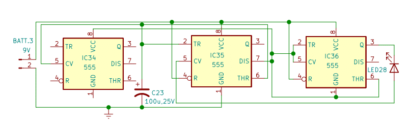
This is a ‘fractured circuit’ of an astable multivibrator. Again no external resistance is used here. Internal resistances of IC34 and IC36 provide a charge and discharge path for the capacitor C23. Only the internal comparators and flip flops of IC35 are used to make the IC35 act as an astable multivibrator. No output stage of IC35 is used here. So pin 3 is left open. IC36 is used exclusively to show the output of the circuit through its internal output circuitry. Both the internal comparators of IC36 are kept deactivated by connecting pin 2 to pin 5 and pin 6 to pin 1. Pin 1 and pin 6 of IC36 are connected to pin 7 of IC35. Whenever output at pin3 of IC35 goes low, the internal discharge transistor of IC35 at pin 7 provides the ground path and the LED28 goes on and off in synchronous with the astable operation of IC35. The Internal 5K resistances between pin 8 and pin 5 of IC35 act as a current limiter for LED28. Thus 3 different ICs together function as an astable multivibrator!
Experiment 14
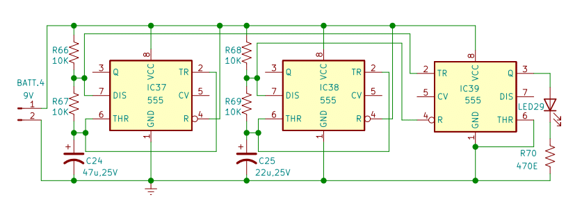
This is a simple but interesting experiment to show the use of the internal discharge transistor at pin 7 of IC555. IC37 and IC38 are wired as astable multivibrators. Output pins 3 of both the ICs are not used. The astable multivibrators are exactly alike except the values of capacitors C24 and C25 differ. IC39 is wired as a bistable multivibrator. Its pin 2 (set) is connected to pin 7 of IC37 and pin 4 (reset) is connected to pin 7 of IC38. Apart from charging the capacitors C24 and C25, R66 and R68 also hold pin 2 and pin 4 of IC39 to the positive rail to avoid false triggering. The internal discharge transistors at pins 7 of IC37 and IC38 provide a negative pulse to set (pin 2) and reset (pin 4) pins of IC39 whenever output at pins 3 of IC37 and IC38 goes low. The LED29 goes on and off alternatively in synchronous with the astable operations of IC37 and IC38 and thus IC39, although wired as a bistable multivibrator, seems to work as an astable multivibrator!
Experiment 15
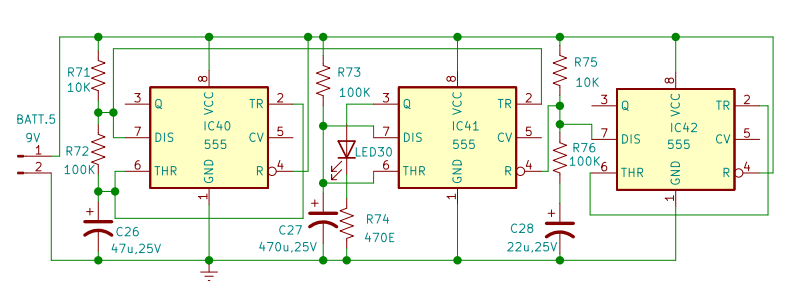
In this experiment, IC41 is wired as a monostable multivibrator and IC40 and IC42 are wired as astable multivibrators. Pin 2 of IC41 is connected to pin 7 of IC40 and pin 4 of IC41 is connected to pin 7 of IC42. Resistances R71 and R75, apart from charging capacitor C26 and capacitor C28, hold pin 2 and pin 4 of IC42 to the positive rail to avoid false triggering. Pin 3 of IC40 and IC42 is not used. Whenever output at pin 3 of IC40 goes low, the internal discharge transistor at pin 7 provides a negative pulse to pin 2 of IC41 triggering the monostable operation. But even before C27 charges to ⅔ of its capacity, pin 7 from IC42 provides a negative pulse to pin 4 of IC41 and resets the monostable operation of IC41 abruptly. And the cycle repeats. Thus the IC41, although wired as a monostable multivibrator, loses its identity and is entirely controlled by IC40 and IC42 keeps it setting and resetting alternately. Since the operation is self-triggering, the IC41, although wired as a monostable multivibrator, appears to act as an astable multivibrator!
Experiment 16
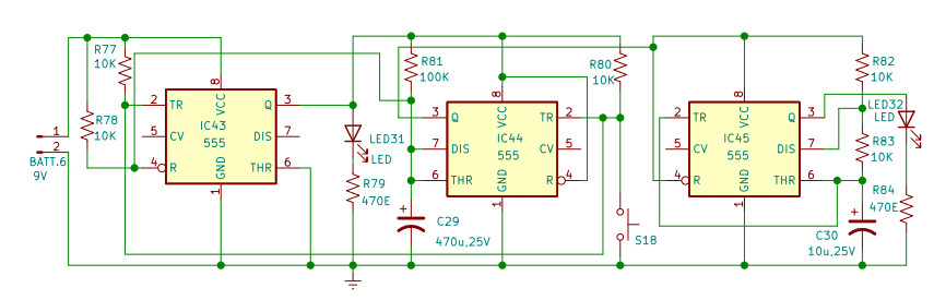
In this interesting experiment, IC43 is wired as a bistable multivibrator, IC44 is wired as a monostable multivibrator and IC45 is wired as an astable multivibrator. IC43 powers the IC44 through its pin 3 and IC44 powers IC 45 through its pin 3. When S18 is momentarily pushed, all three ICs go into action LED31 goes on and LED32 goes on and off. The operation continues till IC44 completes its monostable operation. When output at pin 3 of IC44 goes low, the astable operation of IC45 stops at the same time discharge transistor at pin 7 of IC44 provides a negative pulse to pin 4 of IC43 resetting it, shutting off its bistable operation and cutting off the power supply to IC44. Thus all three ICs in different modes of operation go off and remain off till S18 is pushed momentarily again.
Experiment 17
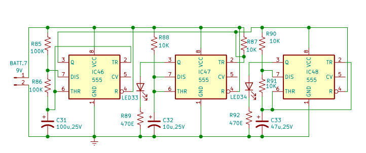
In this experiment, IC46 and IC48 are wired as astable multivibrators. IC47 is wired as a monostable multivibrator. In an astable operation, the output at pin 3 goes high and low alternately. When it goes low, a ground path is made available through pin 3. Taking advantage of the situation, pin 8 of IC48 and pin 2 of IC47 are connected to pin 3 of IC46. When the circuit is powered, the output at pin 3 of IC46 goes high and it powers IC48. IC48 goes into action and the LED34 starts blinking. When output at pin 3 of IC46 goes low, the astable operation of IC48 stops and the monostable operation of IC47 starts as its pin 2 gets grounded and LED33 glows. Once pin 2 gets triggered, it is immune to retrigger unless the monostable multivibrator completes its cycle. Since the time delay is kept low by using low values R88 and C32, the cycle completes soon. However, since the output at pin 3 of IC46 is low, the monostable operation restarts almost immediately also often and often till the output at pin 3 of IC45 goes high and LED33 keeps glowing continuously. Thus monostable and astable operations of IC47 and IC48 are initiated and continued alternately through the same pin 3 of IC46!
Experiment 18
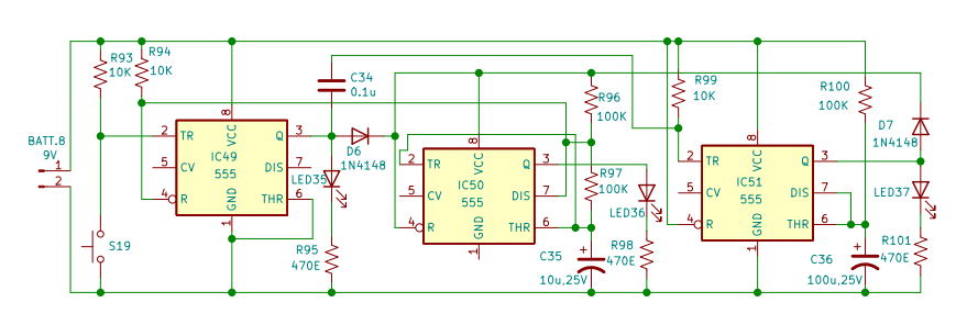
This experiment is a bit complicated. Here IC49 is wired as a bistable multivibrator, IC50 as an astable multivibrator and IC51 as a monostable multivibrator. When S19 is momentarily pushed, IC49 momentarily ‘kick-starts’ the circuit LED35 goes on and at the same time, IC49 powers IC50 and IC50 starts its astable operation. LED36 goes on and off but when output at pin 3 of IC50 goes low at its very first cycle, its pin 7 provides a negative pulse to pin 4 of IC49 and the bistable operation of IC49 resets and stops. LED35 goes off. However, a negative pulse triggers pin 2 of IC51 through capacitor C34 to start the monostable operation of IC51. LED37 goes on and IC51 starts supplying power to IC50 to continue its astable operation. LED36 continues going on and off. The operations of IC50 and IC51 continue till the mostable cycle of IC51 continues and then both ICs IC50 and IC51 go off and remain off till S19 is momentarily pushed again. Diodes D6 and D7 prevent short circuits when output at pin 3 of IC49 and IC51 goes low. Thus IC49 kickstarts the unit to power IC50 momentarily and then IC51 takes over and keeps powering IC50.
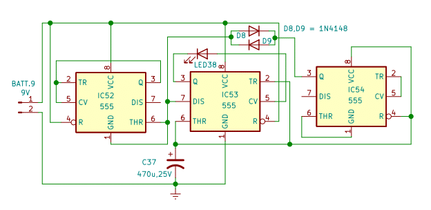
Experiment 19
This non-conventional experiment gives a scope to learn the internal structure of IC 555 to know how the current flows inside the IC. In contrast to Experiment 13(A), where the internal passive resistive network of IC28 and IC29 is used to charge and discharge capacitor C22, here the internal transistorised output stage and voltage divider of IC52 and IC54 are used to charge and discharge capacitor C37. Internal 5K resistance from pin8 to pin5 of IC is used as a current limiter, so no external current limiting resistance is needed for LED 38. Since only the internal output stages and voltage divider of IC52 and IC54 are used, the internal comparators of both the ICs are kept inactive by connecting pin2 to pin5 and by connecting pin6 to pin1. IC53 is wired as an astable multivibrator but no external resistances are used here as internal transistorised output stages and voltage dividers of IC 52 and IC 54 do this job. IC52 gets its ground through pin7 of IC53 while IC54 gets its ground through pin7 of IC53. When the circuit is powered, C37 starts charging. The current flows from pin1 of IC52 to pin3 of IC54 and then from pin8 to C37 to fill it to ⅔ of its capacity. While discharging, the active internal transistorised path of the output stage and of IC54 discharges C37 from pin3 of IC54 and gets it ground through pin7 of IC53. So pin3 of IC54 is used both, for changing and discharging of C37. As IC53 is wired as an astable multivibrator, LED38 starts flashing. Diodes D8 and D9 are optional. Pin3 of IC54 can be directly connected to pin7 of IC 53. However, the diodes are deliberately used here not only to help understand the charging and discharging path of C38 but also one important feature of IC555. Output pin3 of IC555 can ‘send out or take in’ the current. If D8 is disconnected, LED38 will remain continuously on and if D9 is disconnected, LED38 will remain continuously off.
Experiment 20
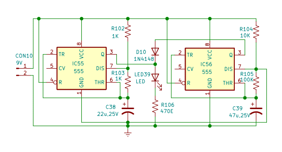
In this unique circuit, two IC 555s are used. Both are wired as ‘Astable multivibrator’. The RC factor of both the circuits varies, however, the output load connected to pin 3 of both the ICs, which is 5 mm LED, is common. (The ‘RC factor’, here, refers to two resistances and one capacitor of each independent astable multivibrator.) When the circuit is powered, LED 39 glows as per timing decided by the RC factor of IC56 and then flashes as per the timing decided by the RC factor of IC55. Thus LED 39, as a common load, glows and flashes alternately and the cycle continues. The RC factor of IC56 has to be always much higher than the RC factor of IC55.
In the circuit, pin 1 of IC55 is connected to pin 7 of IC56. When the circuit is powered, LED 39 glows as the capacitor C39 starts charging. When capacitor C39 charges to ⅔ of its capacity, it starts discharging due to internal comparators and LED 39 starts flashing as the internal discharge transistor at pin7 of IC56 turns on and starts discharging C39 at the same time, almost instantly, it provides a ground path to IC55 and IC55, as an astable multivibrator, starts its operation. Since the RC factor of IC55 is much lower as compared to the RC factor of IC56, LED 39 starts flashing rapidly. This continues till capacitor C39 discharges to ⅓ of its capacity when the internal transistor at pin7 of IC56 turns off and capacitor C39 starts charging again and the ground path to IC55 cuts off instantly and the circuit of IC55 stops. In this manner, the cycle keeps repeating. Diode D10 prevents short circuits through pin 3 of IC56 when IC55 is in operation and hence is important.
Part list
Semiconductor:
IC28 – IC56 IC timer 555
LED24 – LED39 LED 5mm white
- D6 – D10 Diode IN4148
Resistances: (All ¼ watt, +/_ 5% carbon)
- R102,R103,R104 1K
- R66,R67,R68,R69,R71,R75,R77,R78,R80,R82,R83,R87,R88,R90,R91,R93,R94,R99,R104
10K - R72,R73,R76,R81,R85,R86,R96,R97,R100,R105 100K
- R70,R74,R84,R89,R92,R95,R98,R101,R106 470E
Capacitors: (Electrolytic)
- C30,C32,C35 10uF25V
- C25,C28,C38 22uF25V
- C24,C26,C33,C39 47uF25V
- C22,C23,C31,C36 100uF25V
- C27,C29, C37 470uF25V
- C34 0.1uF polyester 50V
Switches
S18,S19 push-to-on
Miscellaneous
Breadboard, hookup wire, 9VDC battery, 9VDC battery terminals.