 A self-made audio power amplifier for a guitar or violin should be simple, low-cost and reliable. It is good to have two separate loudspeakers pointing in different directions. It is better when the amplifier has two separate channels working independently, either paralleled or as a bridged amplifier. This article presents a simple two channel amplifier using two LM1875 audio amplifiers.
Two Channel Amplifier Circuit
Circuit diagram of the simple two channel audio power amplifier for a microphone and two guitars built around three transistors and two LM1875 ICs is shown Fig. 1.
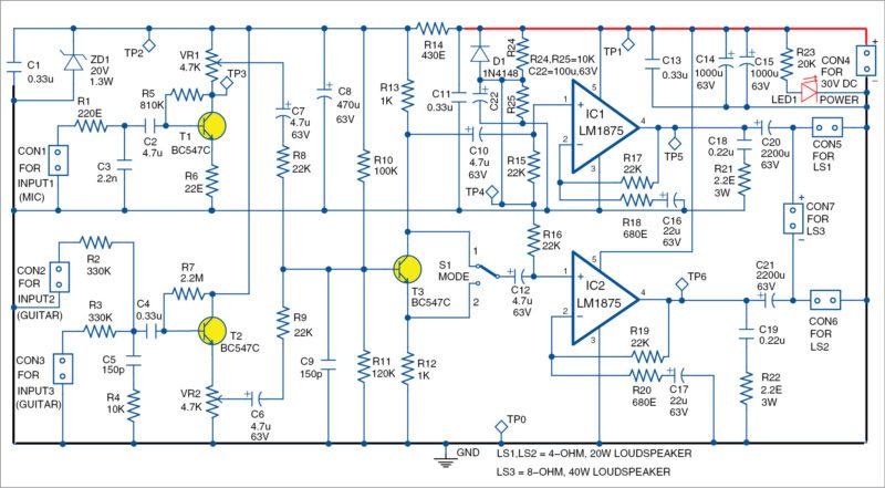
The amplifier has two different input stages that use transistor T1 for a microphone and T2 for two guitar inputs. The mixing stage is built around T3 and two power amplifiers around IC1 and IC2. You can use any of the power amplifier ICs listed in Table I.
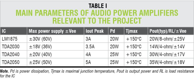
There are many low-cost power amplifier ICs having 10W – 50W or more peak-output power. Even though some of these ICs produce sufficient power for small guitars and violins, it is a good idea to combine two ICs for more output power and the possibility to drive one or two systems with loudspeakers.
When a single load is driven, both the amplifiers could be bridged. Theoretically, if two power amplifiers are bridged, the output power increases four times. Practically, there are limitations imposed by the parameters of the ICs. More information about bridging is provided in the datasheets of respective ICs.
Selection of ICs from Table I will determine the minimum and maximum power supply, minimum output load resistance, maximum output and maximum power dissipation of the semiconductors.
Connectors
This two-channel amplifier has seven connectors (CON1-CON7). There are three inputs (CON1-CON3), three outputs (CON5-CON7). CON4 is for power supply. Input signal from a microphone is applied to CON1 and is amplified through T1. Gain of the stage is above 100 and depends on potmeter VR1 and resistor R6.
CON2 and CON3 are for inputs to guitars. Resistance of a single input is above 1-mega-ohm.
Values of R2 and R3 are selected according to the guitar pickups. T2 works as emitter follower with gain close to unity. T1, T2 and T3 should be of low-noise and high-gain type such as BC109C, BC547C or BC550C.
Signals from all inputs are summed in T3 stage, which provides two output signals with the same amplitude but with opposite phases. These signals are applied to two identical output stages built around IC1 and IC2.
Switch S1 gives the option to select the same or opposite signals for the stage using IC2. Both output stages are identical. These can be driven with the same or with opposite signals. Gain of the output stage is around 33 and can be readjusted with feedback resistors as needed.
Mode-control switch S1
The amplifier has several configurations depending on the position of S1 and connection of loads. S1 has two positions, 1 and 2.
When S1 is in position 1, both output stages have the same input signals. Loads have two configurations. In the first configuration, two separate loads (loudspeakers) can be connected to CON5 and CON6.
In the second case, CON5 and CON6 can be paralleled through small equalisation resistors (usually 0.05-0.1-ohm load resistance) and a common load can be applied.
This is possible because output stages have very close parameters. Gain-control resistors should be matched to better than ±1%. Care must be taken about polarity of signals and polarity of connections of loudspeakers.
When S1 is in position 2, output channels are driven by opposite signals. Here also, there are two possible configurations for loads. In the first case, two separate loads can be connected to CON5 and CON6.
In the second case, CON5 and CON6 are not used, and only a single load is connected to CON7.
In both cases, load can be from 4-ohm to 16-ohm (sometimes even more), and its resistance and power depends on the ICs selected from Table I.
Power supply
DC power supply is applied to CON4 as per power amplifier ICs selected from Table I. Power supply can be regulated or unregulated.
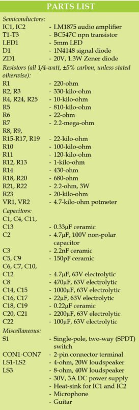
Values of capacitors C11, C13, C14 and C15 can be increased or paralleled with additional capacitors. Power supply for the transistors is additionally filtered and regulated with Zener diode ZD1, capacitors C1 and C8 and resistor R14. Zener ZD1 is BZX85 type with maximum power of 1.3W, depending on the selected power supply.
Heat-sink
IC1 and IC2 are mounted on appropriate common heat-sinks, depending on the required output power. It is preferable to use heat-sinks with thermal resistance lower than 1.5oC/W. Bigger heat-sinks are better.
Construction and Testing
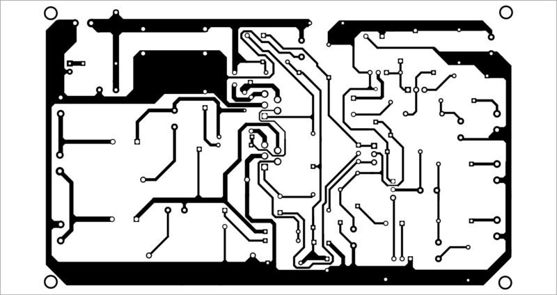
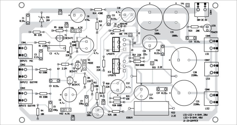
A single-side PCB pattern for the simple two channel amplifier is shown in Fig. 2 and its component layout in Fig. 3.
Download PCB and component layout PDFs: Click here
The loudspeakers can be 4-ohm to 16-ohm, peak-output current can go up to 3A or even 5A in some cases, and peak-output power is from 10W to more than 40W, depending on the selected ICs, heat-sinks, power supply and configuration of output (dual-way or bridged amplifier).
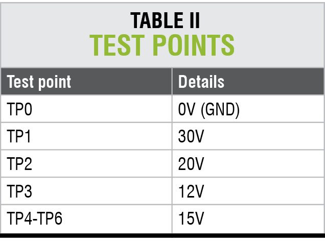
This power amplifier usually does not need any adjustment, but it is important to have the gains of the output stages as mentioned earlier. For troubleshooting, check voltages at various test points listed in Table II.
Petre Tzv Petrov was a researcher and assistant professor in Technical University of Sofia (Bulgaria) and expert-lecturer in OFPPT(Casablance), Kingdom of Morocco. Now he is working as an electronics engineer in the private sector in Bulgaria.


Hi Petre, thanks for this project – I would like to build it. Do you have a Parts List for this project?
Regards,
Brian
Hi! Thank you for posting this project online. I plan to use it in my class. We will be building a PCB. May I please get the parts list? – AVV
Thank you for your comment, the article is updated with the parts list
Thanks for this simple project..but please mention the advantages and disadvantages ..because it is very helpful l to the beginners..like us….
Lm1875, Tda2030A, TDA2040, TDA2050 etc is giving 6 watts @ 4 ohms load on 24 volts 2 ampere supply even after using large heatsink. So I expect a maximum of 10 watts on 30 volts with the same load. However, it may output more power on split supply than on single supply
How can I use this circuit to connect three Microphones and one usb mp3 module with all four sources working simultaneously ?