


In this project, we will be using the ESP8266 – 01 Wi-Fi Development board to make a small IoT home automation that has Wi-Fi featured in it. The system operates on a local web server and is easy to use for the novice. With this project, we can control at most two AC appliances which suit best for your small IoT projects.
Espressif developed Wi-Fi enabled microchip – ESP8266 proved to be a boon in the IoT field. This caused the arrival of various other ESPs and Open Source Development boards thereby allowing even a novice to make Wi-Fi featuring applications.

On a local web server, we do not require Internet and handling everything over Wi-Fi is possible. Here, we will be handling the two Input & Output pins and switching relays on a web page of the local server. We can connect our home appliances with the Relay Module that will be driven by ESP8266 – 01.
Material required for the IoT project
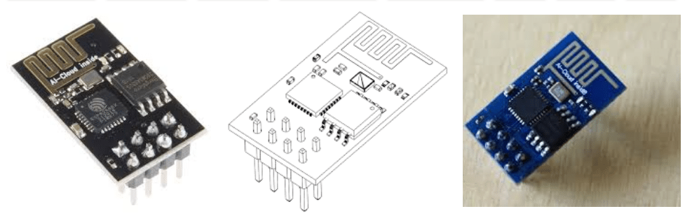
- ESP8266 – 01: It will serve as the brain of our project.
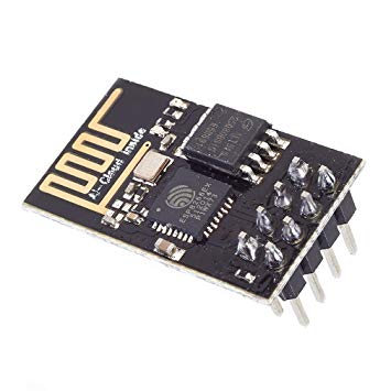
Fig. 2: ESP8266 – 01 - FTDI Board (USB to TTL): To upload code in ESP8266 – 01.
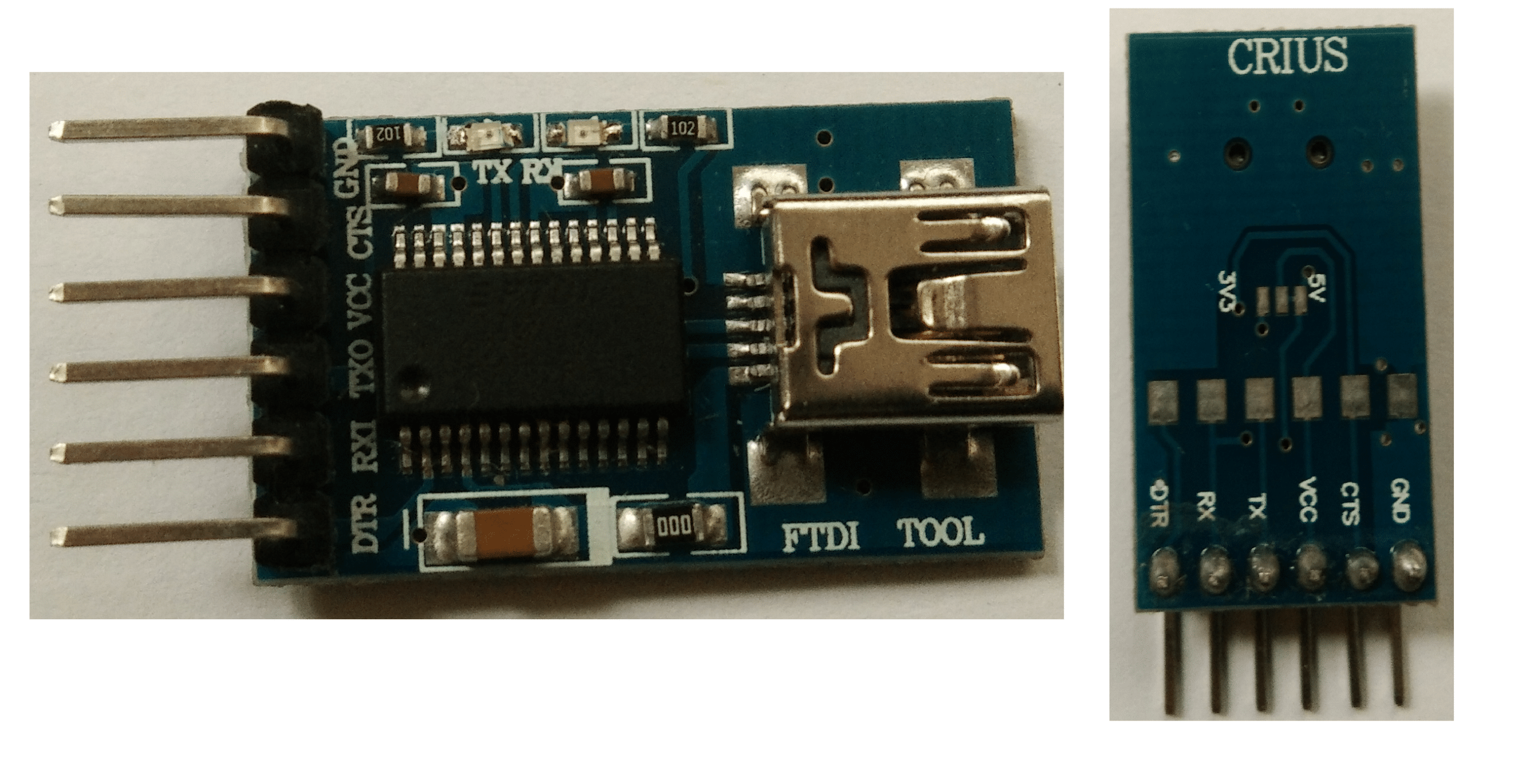
Fig. 3: FTDI Board - 2 AC Appliances
- One(1) 2-Channel Relay Module
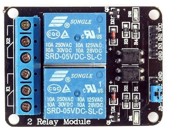
Fig. 4: 2 Channel relay module - Breadboard with some wires.
Steps for the ESP8266 Setup in Arduino IDE
(Ignore this step if you already have the setup for Arduino IDE)
To code the ESP8266 we need an Integrated Development Environment and we will use Arduino IDE software. Arduino IDE is a cross-platform application. It is written in Java and coded in C/C++ with some special rules. To download the latest Arduino IDE click here.
Arduino IDE does not contain support of ESP8266 family so to install the ESP8266 Boards library in Arduino IDE, follow the instructions below.
- Open Arduino IDE. Go to File > Preferences.
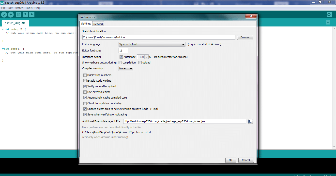
Fig. 5: Preferences in Arduino IDE - Enter http://arduino.esp8266.com/stable/package_esp8266com_index.json into the “Additional Board Manager URLs” field. Now, click the “OK” button.
- Go to Tools > Board > Boards Manager.
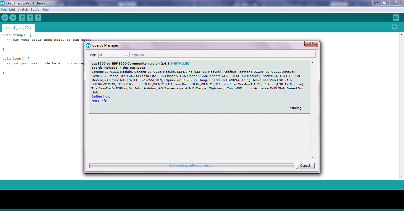
Fig. 6: Boards manager in Arduino IDE - Search and scroll down ESP8266 board in menu and install “esp8266 by Esp8266 community”.
- Select your ESP8266 board from Tools > Board > Generic ESP8266 Module.
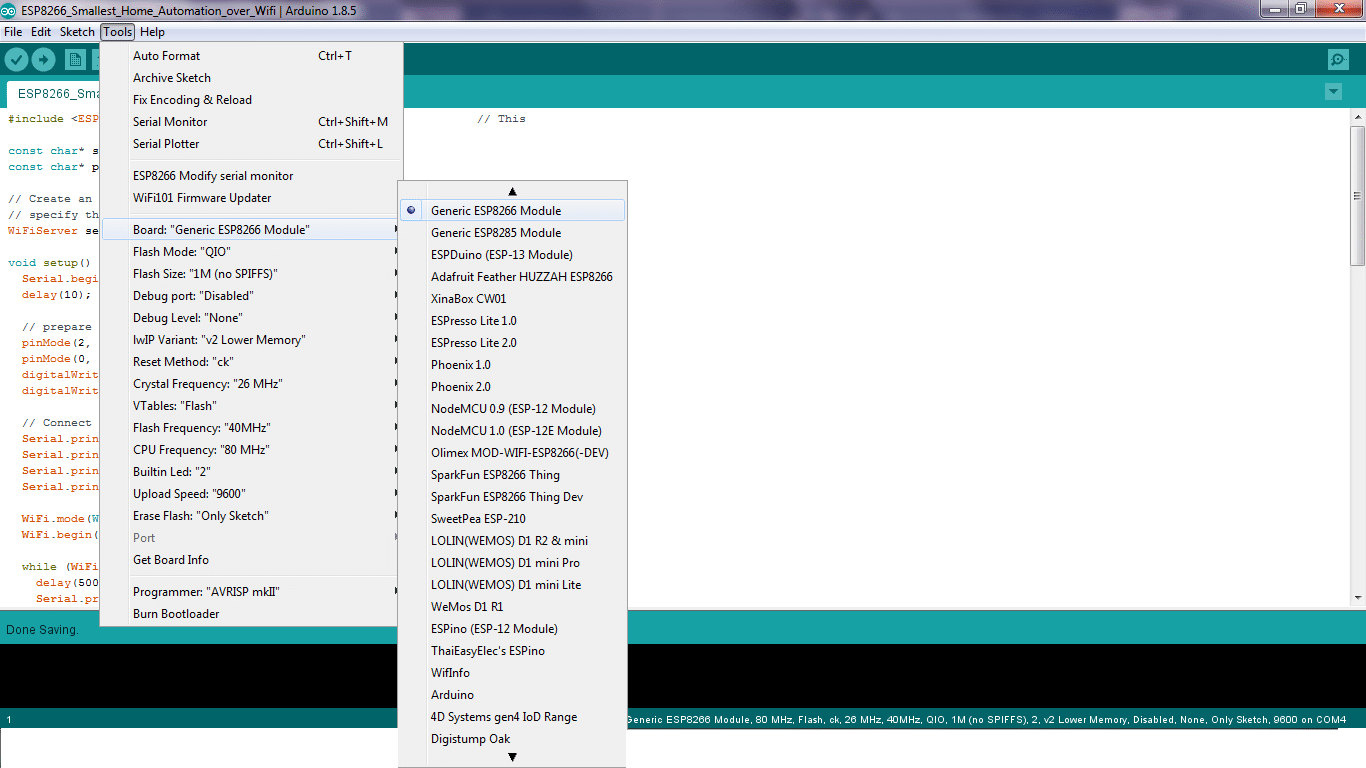
Fig. 7: Board Selection in Arduino IDE - Restart your Arduino IDE.
Source Code of the IoT project
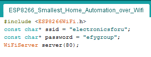
Download the Code from the link below and Open it in Arduino IDE. Before uploading you need to make some changes in the code. Let’s understand the code.
Place your Wi-Fi credentials here within the double quotes. The <ESP8266WiFi.h> library helps to run the functions of Wi-Fi in Arduino IDE.
In the void setup(), we place all the one-time setup codes. All the instructions written here will run only once or after every Reset.
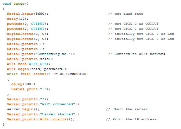
So, the GPIOs 0 and 2 of ESP8266 are made OUTPUT here and the server is started.
Void loop() is the place for the main executable instructions. The GPIO values are changed here as per the request of the client connected.
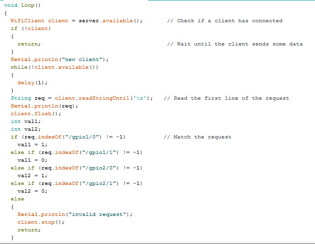
This request is displayed via this HTML page.
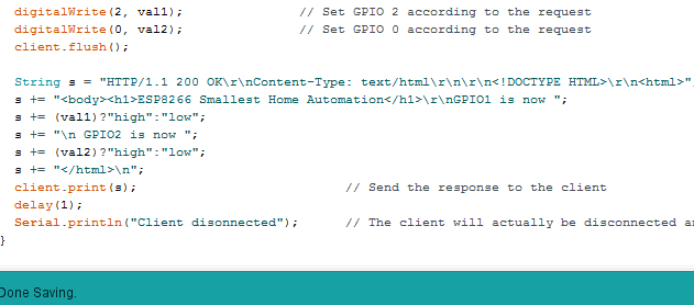
Save the Code. To Upload the code, follow the instructions below.
- Connect the FTDI pins to ESP8266 as shown below.
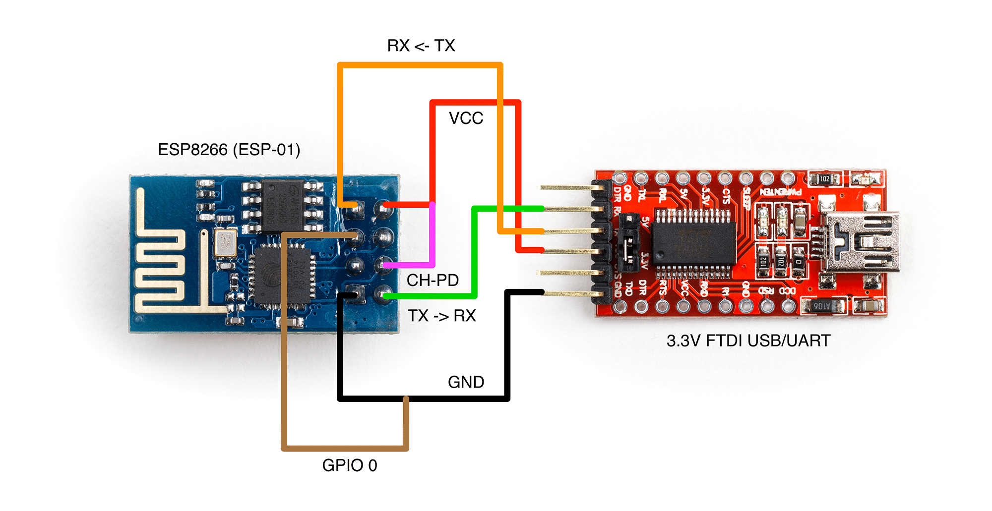
Fig. 12: Flashing ESP8266 – 01 - Select your COM Port from Tools > Port after connecting FTDI USB to your PC or Laptop.
- Also, check if your ESP8266 supports 9600 or any other Baud Rate.
- Now Click Upload.
The code in ESP8266 is uploaded in Flash Mode, which is when GPIO 0 is grounded.
Now, to run the code in it, we need to remove it from Flash Mode. For this, simply remove GPIO 0 from the ground and Reset.
To Reset ESP8266, simply touch the Reset Pin of ESP8266 to Ground for half a second. Its Blue LED will flicker.
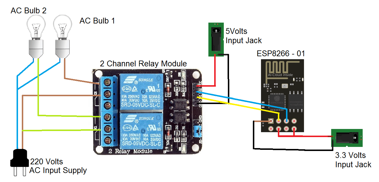
Circuit diagram for Home automation
Flow the circuit diagram for making the home automation system.
GPIO 0 -> Relay IN 1
GPIO 2 -> Relay IN 2
We will use 5 volts input supply for driving the Relay Module and 3.3 Volts Input for the ESP8266.
Connecting to the web using the IP address
After uploading the code, go to Open Tools>Serial Monitor. ESP8266 will try to connect to Wi-Fi and display its IP address on Arduino serial monitor. This IP is needed only the first time. The IP remains the same forever so have this IP before making the main connections.
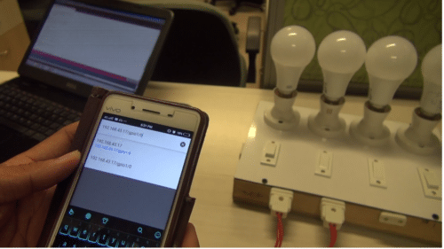
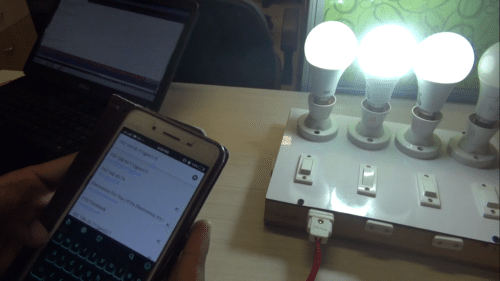
Make sure that the Wi-Fi router to be connected is already open. Hit this IP address in the browser of the device connected to the same Wi-Fi.
Url: http://192.168.xx.xx (your IP displayed in Arduino serial monitor)
You will be able to see the HTML Web page mentioned in the code.
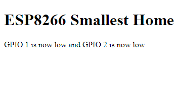
Now, by changing the values in the URL you can switch your appliances.
Try with,
http://<your IP address>/gpio1/0
http://<your IP address>/gpio1/1
http://<your IP address>/gpio2/0
http://<your IP address>/gpio2/1
To download the source code click here.
To purchase the components for this project visit kitsNspares.

Hello,
I have done the relay connection as said, but the switching doesn’t happen.
Irrespective of the input to the relay, the output bulb stays as it is.
Can you please help me out with this?
using this module how many relay we can controll
I guess you have to make both the grounds common for it to work
will i be able to control home appliances from any where in the world
or i will have to connected to the same wifi set up
Same Wifi
sir can i use nodemcu8266 in place of esp8266 ?
and
if i increase the output relays, then how ?
If i want to use my Mobile hot spot , what will be the Ip address? how to find it.
With the ESP-01S-Relay-v1.0 module, I want to use my home lamp both from WiFi and manually.
I want to turn it on and off from the wifi while the lamp switch is off.
How can I do that? Can you help me.