


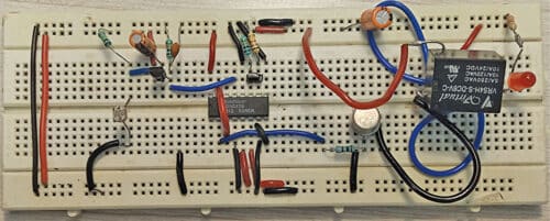
 Specially Abled persons, without hands or feet, often find it difficult to switch on an appliance. This switch can come to their rescue. It can be operated with a torch light or a laser light by those who are unable to use their feet, and with a footswitch by those who are unable to use their hands, to operate home appliances, fixtures, toys, learning devices, and other gadgets. The author’s circuit wired on a breadboard is shown in Fig. 1.
Circuit diagram of the switch for the specially abled is shown in Fig. 2. The circuit comprises a bridge rectifier (BR1), 12V voltage regulator 7812 (IC1), dual flip-flop 4027 IC (IC2), 12V one-changeover relay (RL1), a foot switch (S1), and a few other components. Capacitors connected across the supply terminals are used to minimse any noise signals.

A mains 230V AC primary to 15V, 500mA secondary transformer (not shown in Fig. 2) may be used to step down the AC mains voltage to 15V AC. This voltage, connected across CON1 in the circuit, is rectified by bridge rectifier BR1 and filtered by capacitors C1 and C2 to remove any ripples in the voltage. The rectified and filtered voltage is then regulated by IC 7812 (IC1) to provide 12V DC to operate the circuit.

The LDR’s resistance varies with the intensity of light falling on it. When the light falling on LDR increases, the LDR resistance decreases, and when the light falling on LDR decreases, its resistance increases. In darkness, when there is no light, the resistance of LDR is in the range of mega ohms, but in presence of bright light it decreases to a few hundred ohms.

IC 4027 has flip-flops IC2A and IC2B that are used for data storage. IC2C is its power supply terminal. The square wave generated by flip-flop IC2B is coupled to flip-flop IC2A, whose output is given to relay driver transistor T1 to drive relay RL1.
| Parts List | |
| Semiconductors: | |
| IC1 | – LM7812, 12V voltage regulator |
| IC2 | – 4027 dual flip-flop IC |
| BR1 | – 1A bridge rectifier |
| T1 | – BC557 pnp transistor |
| T2 | – SL100 npn transistor |
| D1 | – 1N4007 rectifier diode |
| LED1 | – 5mm LED |
| Resistors (all 1/4-watt, ±5% carbon): | |
| R1, R6 | – 1-kilo-ohm |
| R2 | – 100-kilo- ohm |
| R3, R4 | – 10-kilo-ohm |
| R5 | – 18-kilo-ohm |
| Capacitors: | |
| C1 | – 1000μF, 35V electrolytic |
| C2 | – 1μF, 25V electrolytic |
| C3 | – 0.1μF ceramic disc |
| Miscellaneous: | |
| LDR1 | – Light dependent resistor (LDR) |
| RL1 | – 12V, 1CO relay |
| S1 | – Foot switch |
| X1 |
– 230V AC primary to 15V, 500mA secondary transformer
|
| CON1-CON3 | – 2-pin terminal |
| – Torch or laser light | |
When a foot-disabled person focuses torch or laser light on the LDR, it triggers flip-flop IC2 and its output goes high at its pin 2, which energises relay RL1 via relay driver transistor T1. As a result, the home appliance gets 230V AC supply and switches on. When the light is focused once again on the LDR, it re-triggers flip-flop IC2 and now its output goes low at its pin 2 and relay RL1 de-energises via transistor T1. As a result, the home appliance now gets disconnected from 230V AC and switches off.
Similarly, when a hands-disabled person presses foot switch S1, it triggers flip-flop IC2 and its output goes high at its pin 2, which energises relay RL1 via relay driver transistor T1. As a result, the home appliance gets 230V AC and switches on. When switch S1 is pressed again, it re-triggers flip-flop IC2 and its output goes low at its pin 2, which de-energises relay RL1 via transistor T1. As a result, the home appliance gets disconnected from 230V AC and switches off.
Construction and testing
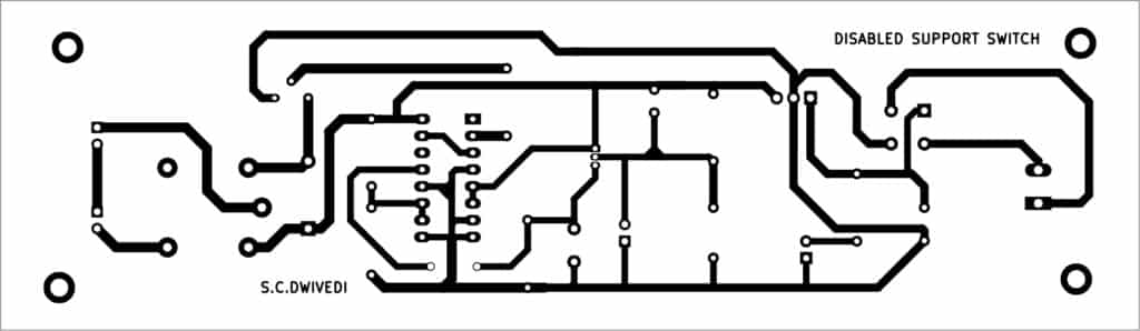
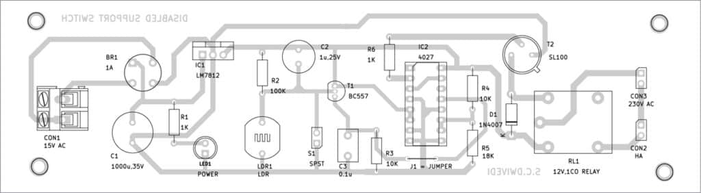
An actual-size, single-side PCB for the switch is shown in Fig. 3 and its component layout in Fig. 4. After assembling the circuit on PCB, enclose it in a suitable box. Connect LDR in front of the box and extend the foot switch to the disabled person’s chair using a flexible wire.
After proper installation, connect 230V AC mains to primary terminals of the transformer and 15V AC secondary terminals across CON1. The circuit is now ready to use, provided the LDR has been installed at the domestic switchboard and the foot switch has been extended up to the disabled person’s chair.
Bonus. You can watch the video of the tutorial of this DIY project
Download PCB and Component Layout PDFs: click here
S.C. Dwivedi is an electronics enthusiast and circuit designer at EFY
