


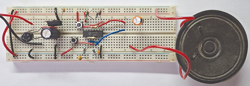
In modern homes, apartments, and offices, multiple entrance doors are common. Traditionally, each door requires a separate doorbell, which increases cost and can confuse residents. Hearing a bell without knowing whether it is the main entrance or the back door is a frequent inconvenience. To address this, a single bell device has been designed for two doors, using a common bell that produces two distinct sound patterns depending on which door’s switch is pressed. Fig. 1 shows the device prototype without its transformer.
POC Video Tutorial:
| Parts List |
| Semiconductors: IC1 – LM7805, 5V regulator IC2 – LM556 timer BR1 – 1A bridge rectifier Resistors (all 1/4-watt, ±5% carbon): R1, R2, R4, R5 – 1kΩ R3 – 68kΩ R6 – 22kΩ Capacitors: C1 – 1000µF, 35V electrolytic C2, C4 – 100nF ceramic disc C3, C5, C6 – 10nF ceramic disc C7 – 220µF, 35V electrolytic Miscellaneous: CON1 – 2-pin connector LS1 – 8Ω, 0.5-watt speaker S1, S2 – Bell switch X1 – 230V AC primary to 15V AC, 500mA secondary transformer |
Circuit and Working
Fig. 2 shows the circuit diagram of the dual-tone single bell device for two doors. It uses a popular LM556 dual-timer IC, which has two 555 timers built into one package. The entire circuit is divided into three sections: the power supply section, the tone generation section, and the output section.
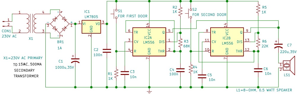
The power supply section is built around transformer X1 and LM7805 (IC1) and provides a regulated 5V DC supply. A step-down transformer (X1) reduces the mains 230V AC voltage to 15V AC, which is then rectified by a bridge rectifier (BR1). An electrolytic capacitor (C1) smooths the DC output, while another capacitor (C2) removes high-frequency noise. Finally, the LM7805 voltage regulator ensures a steady and ripple-free 5V DC, which powers the LM556 timer IC and associated components.

The tone generation section, built around LM556 (IC2), produces two tones. This IC has two inbuilt timers in a single package. Both are configured in astable mode to generate oscillating signals. The first timer (IC2A) is activated when switch S1 is pressed at door 1. Its frequency is determined by resistors R2 and R3 and capacitor C4, producing a specific tone. Similarly, the second timer (IC2B) is triggered by switch S2 at door 2, and its frequency is set by resistors R5 and R6 and capacitor C6. Due to the difference in tones, one can easily distinguish which doorbell has been activated.
Tone 1 is set by resistors R2 and R3 and capacitor C4 around IC2A. Increasing C4 decreases the frequency to produce a lower-pitched tone, while decreasing it increases the frequency for a higher-pitched tone. Adjusting R2 also changes the tone inversely with frequency.
Tone 2 is set by resistors R4 and R5 and capacitor C6 around IC2B. Increasing C6 lowers the frequency for a deeper tone, while decreasing it raises the frequency for a sharper tone.
The output section, built around a common speaker (LS1) and capacitor C7, produces two distinct tones. The speaker converts the oscillating square-wave signals into audible sounds. Because the timers generate different frequencies, the speaker emits two clearly distinguishable sound patterns. This ensures that, with a single speaker, residents can easily identify which doorbell switch has been pressed, based on whether the sound is higher-pitched or lower-pitched.
Overall, the power supply provides a stable 5V DC to the circuit. Pressing switch S1 triggers IC2A, producing Tone 1, while pressing switch S2 triggers IC2B, generating Tone 2. The speaker then rings at the corresponding frequency. Since both tones are distinct, the listener can quickly recognise whether the call is from door 1 or door 2. This makes the device simple, practical, and highly efficient for homes, apartments, or offices with more than one entrance.
Construction and Testing
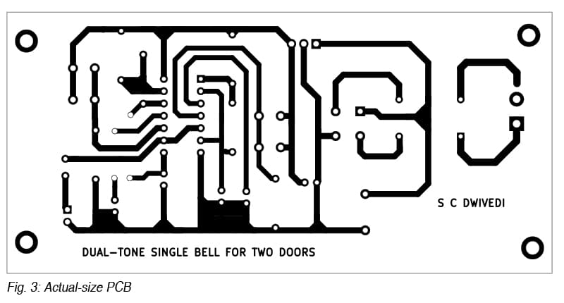
An actual-size, single-sided PCB layout for the dual-tone single bell device for two doors is shown in Fig. 3, with its component layout in Fig. 4. After assembling the circuit on the PCB, enclose it in a suitable box.
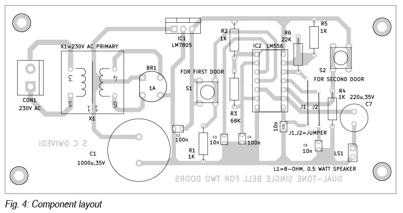
For PCB assembly, start with small parts, such as resistors, ceramic capacitors, and jumpers, followed by the rectifier, regulator IC, timer IC, and electrolytic capacitors. Mount connectors for AC input, speaker, and switches, and solder them. House the assembled PCB in a plastic enclosure with external connections for the transformer, switches, and speaker.
For testing, first check the regulated 5V output with the LM556 removed. Once verified, insert the LM556 and connect the speaker. Pressing switch S1 should give Tone 1, while S2 produces a distinct Tone 2. If both sound similar, check the resistor and capacitor values. If silent, check the supply and IC connections. After confirming operation, install the switches at the doors and place the speaker centrally.
Installation steps
- Install the door push switches S1 and S2 at the entrances
- Mount the speaker (LS1) at a central location inside the house where it is clearly audible, ensuring it is securely fixed and protected
- Connect the 230V AC input to connector CON1 and keep the cabinet in a suitable place
- Connect the speaker to the output connector LS1
- Insulate all AC parts and test the system.
Bonus: You can watch the complete video tutorial of this project.