


Three different MMS schemes are available: Miller-2, Miller-4 and Miller-8. The number specifies how many BLF periods define a data symbol. For example, using the slowest BLF of 40 kHz, the data rate for Miller-8 is BLF/8 = 5 kbps. At such a slow rate, transmitting a 96-bit EPC and 16-bit error check will take 22.4 ms, corresponding to less than 45 tag reads per second (even fewer when all the overhead, such as the forward link commands, is included). Transmitting at this slow rate is not desirable for throughput reasons, but also because some regulations (The United States FCCs’ Part 15, for instance) allow operation at a single frequency only for an average of 400 ms within a 10- or 20-second period depending on the 20dB bandwidth of the signal. This regulation may require the tag reader to vacate the channel after 400 ms and hop to a different frequency even if not finished with reading at that frequency.
Readers and tags operating in conformance to ISO18000-7 take a different approach. These use longer RF transmissions with slower transfer rates, which allows the signal to be more immune to interference. For shipping container applications using the commercial equivalent version ISO 18185, this requires that the maximum transmission duration be increased to 60 seconds while maintaining a 10-second minimum silent period between transmissions (FCC part 15.240). At such slow transfer rates, transferring the full 128 kilobytes of data needed to identify all the contents of a shipping container can take up to two minutes. The tags used in accordance to this standard are active; they have an on-board power supply and tend to radiate at higher power levels than passive tags.
Both of these techniques imply that the testing solution needs to collect detailed RF data on pulsed signals over a relatively long time period.
Testing solutions for a dense-mode environment
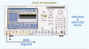
Simulating a dense-mode environment is possible using an arbitrary waveform generator (AWG). Modern AWGs can be programmed to directly generate RFID signals across HF and UHF bands and thus be used to simulate a variety of signals such as multiple reader or multiple tag signals with just one instrument. This reduces the time and cost of having to configure multiple signal generators.
The analysis device often needs quite deep memory to capture all of these lengthy interactions. Typically, the tag reader tries multiple queries and may command the tags to reduce their link frequency to verify that the tags are vacating the channel as required in some implementations. Real-time spectrum analysers (RTSAs) are capable of analysing these types of transactions.
An RTSA can directly verify the 60-second transmission and the 10-second silent period of ISO18000-7, with memory depth of more than 100 seconds in this application. This allows a thorough analysis of error conditions.
It is also possible to use multiple acquisitions to analyse hopping and bursting RFID signals. In this mode, the RTSA is set up to capture data for a user-defined period of time whenever a hop, and the associated trigger, occurs. This, in combination with a very high frame rate (over 48,000 fps), allows capture, analysis and demodulation of a hopping RFID signal.
Once the signal is captured, it can be analysed in a way that helps engineers to understand whether the reader and tag are performing as expected in the current RF environment, and if not, why. Measurements of bit time, CW time, and response time between the reader and the tag (known as turnaround time) give important insight into the reader and tag interaction and throughput. Checking amplitude glitches against frequency events can help spot root causes of errors. If a particular bit is not decoding properly, is it because of an error in the FSK or ASK modulation? Correlating data in various domains helps to answer these types of questions.