


1. Compliance zone (potential exposure to EMF is below applicable limits)
2. Occupational zone (potential exposure to EMF is below the limits for occupational exposure, but exceeds the limits for general public exposure)

3. Exceedance zone (potential exposure to EMF exceeds the limits for both, occupational and general public exposure)
It should always be ensured that for distances greater than the compliance distance, the radiation level is under the limit. It means that if a lower amount of data concerning a radiating source is available, then the higher overestimation of compliance distances is required.
Assessment of exposure levels
The real source of electromagnetic radiation is the transmitting antenna and not the transmitter itself. The transmitting antenna is the main source that determines electromagnetic field distribution in the vicinity of a transmitting station. So, it is required to consider the appropriate region of the field of an antenna.
The space surrounding an antenna is generally subdivided into four regions: reactive near field, reactive-radiating near field, radiating (Fresnel) near field and radiating far field. Radial distance of the reactive near field is 0.62(D3/λ)1/2, where D is the largest dimension of the antenna and λ is the wavelength (to be valid, D must be large compared to the wavelength). Radial limit of the radiating near field is 2D2/λ. The field region beyond radiating near field (distance ≥ 2D2/λ) is radiating far field, where the field pattern is essentially independent of the distance from the antenna. Thus, assessment of exposure level in any field region for mobile phone frequency bands of interest can be easily done.
For assessment of the exposure level, it is required to measure field quantities such as electric field intensity (E), magnetic field intensity (H) and specific absorption rate (SAR). Selection of the field quantity to be measured depends on where (near or far field region) the observer is and on the field impedance. In the reactive near field, it is required to measure both E and H components or evaluate SAR. Determining SAR instead of field measurement is preferable at positions located very close to the antenna. In reactive radiating near field, if no information on the field impedance is available, it is suggested to measure both E and H fields. If information on field impedance is available, it is possible to measure only one field component. If E/H>120π (high-impedance EMF), measurement of component E is required and if E/H<120π (low-impedance EMF), measurement of component H will suffice.
Now, in radiating near field, it is suggested to measure only component E with the impedance taken equal to free-space impedance (Z0). In the radiating far-field region, it is possible to measure either the electric or magnetic field component and determine the equivalent power density. However, measurement devices for the electric field component (E) are usually preferred. The equivalent power density within the far-field region is obtained from the measured field by calculation.
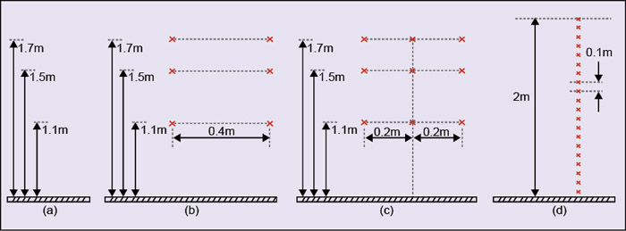
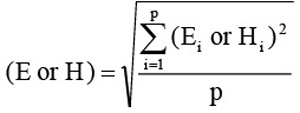
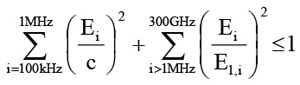
Further, multi-path reflections can create non-uniform field distributions. Therefore, to assess the correct exposure level, an averaging process is required and field values should be determined at several points (p) as shown in Fig. 4. Three points are basically recommended (Fig. 4a), but if accuracy is required the number can be increased to six (Fig. 4b), nine (Fig. 4c), 20 (Fig. 4d), etc, for more accurate results. In case of multiple sources, the measurement area should be divided into a grid of about one square metre and measurements should be performed at individual grid points.
The spatially-averaged field value is given by:
In most cases, a typical transmitting station contains many transmitting systems operating on many frequencies. In this scenario, all operating frequencies must be considered in a weighted sum, where each individual source is pre-rated according to the limit applicable to its frequency. For simultaneous exposure to fields at different frequencies of our interest (GSM, CDMA, 3G, WiMAX, etc), the compliance with exposure limits is evaluated as:
where, Ei is the electric field strength at frequency i, El,i is the reference limit at frequency i, c = 610/f (f in MHz) for occupational exposure and (87/f)1/2 for general-public exposure.
Assessment of exposure levels can be done either by measurement or by numerical calculations or by electromagnetic software simulations. All these methods have almost similar level of uncertainty and accuracy, depending on the method and equipment or software used.
Radiation mitigation techniques
If the electromagnetic radiation level in any area accessible to people is higher than prescribed limits, it is strongly required to take necessary action to reduce the radiation level. To achieve the required reduction of radiation level, several mitigation techniques may be applied, either individually or simultaneously.
1. Transmitter power reduction. The transmitter power is directly related to the power density and square of the electric field strength/magnetic field strength. So, reduction in transmitter power would result in reduction of radiation level. But, this method also leads to reduction of the coverage area.
2. Increase in antenna height. The power density at any observation point is the function of antenna height. If the antenna height is increased, then the power density/field strength at the observation point is reduced due to an increase in the distance to the point of observation. The reduction of radiation level is even greater because at the same time elevation angles to the considered area are moved to another part of the vertical radiation pattern of the antenna.
3. Decrease in VRP downtilt. The vertical radiation pattern (VRP) of an antenna is very important for performance improvement. All energy radiated above the horizontal plane is lost, and this loss can be managed by reducing the VRP and downtilting the beam. The main beam is tilted downward in order to limit the coverage area, which also increases the possibility of frequency re-use. Moreover, the radiation level also increases in the proximity of antenna. So, it is advised to decrease VRP downtilt in order to reduce the radiation level. The downtilt of the main beam can be achieved by either mechanically or electrically-operated motor mechanism.
4. Increase in antenna gain. Gain of an antenna is a key performance figure that combines the antenna’s directivity and electrical efficiency (G=ηD(θ,φ)). It specifies how well the antenna converts input power into electromagnetic waves headed in a specified direction and to limit the radiation in other directions. So, it is possible to limit the radiation level in the area accessible to the people with the control of the directivity (ultimately gain) of the antenna. Again, the directivity of the antenna is related to horizontal radiation pattern (HRP) and vertical radiation pattern (VRP). In order to protect people against radiation, HRP of the antenna can be altered but it will always affect the coverage area.

On the other hand, VRP determines radiation as a function of distance to the antenna. So, antenna gain (or more precisely VRP) can be utilised (increased gain/sharp main lobe) to limit the radiation level in close proximity of the antenna without affecting the coverage area. This can be achieved by feeding a high-gain antenna with a low-power transmitter, which will result in the same amount of equivalent radiated power (ERP). So, it is recommended to use a low-power transmitter with a high-gain antenna (narrower VRP beam width) for attaining a low-level of radiation.
5. Changes in VRP. VRP is a function of elevation angle (i.e., in a vertical plane) and represents the distribution of energy in a vertical plane. It gives an impression of distribution of energy depending on the distance between a transmitting antenna and an observation point. Vertical radiation pattern is responsible for radiation to the area in the proximity of the antenna. So, changes can be done in VRP by introducing changes in the feeding arrangement (changing cable length). So, an optimisation of VRP will result in reduction in radiation level.
6. Changes in HRP. HRP is a function of azimuth angle, representing distribution of energy in a horizontal plane. It is possible to reduce the radiation level by using an antenna with a narrower horizontal beam. A narrower horizontal beam (means higher antenna gain) accompanied with lower transmitter power will result in lower radiation level without the loss of coverage area.
7. Multiple methods applied simultaneously. All methods described above are independent and can be applied either individually or in combination to achieve the required decrease in radiation level.
Placement of signage
It is the responsibility of the wireless service provider to ensure provision of proper signage, warning entry of general public to the exclusion zones. Samples of different signboard are shown in Fig. 5. The danger signboard should be placed on the tower structure. Warning signboard should be placed at the entry point of the exclusion zone and the caution signboard should be placed at the entrance of the base station compound in case of ground base tower (GBT) or at the entry point of the roof of the building in case of roof-top tower (RTT).
Conclusion
Operators providing wireless communication should seriously consider this study and ITU-T recommendations in order to keep the operation of base-station transceivers in compliance with regulations concerning environmental protection against non-ionising radiation. Further, it is important to note that the present threshold limits prescribed by ICNIRP are considered to be rather too generous. Hence, there is a need to review and remedy the situation and not wait until it becomes the subject matter of a public-interest petition in the light of possible environmental adverse effects.
In order to minimise possible health hazards, some recommendations are: minimisation of mobile phone usage, limitation of use by at-risk population (such as children), adoption of mobile phones and microcells with as low as reasonably-practicable levels of radiation, wider use of hands-free and earphone technologies such as Bluetooth headsets, headsets with ferrite beads and headsets with air tube, adoption of maximal standards of exposure and greater distances of base-station antennae from human habitations, and so forth.
The author holds a Ph.D. in electronics engineering from IIT (BHU), Varanasi, and is currently assistant professor at Lovely Professional University, Pubjab. Perviously, he was associated with BSNL. He has received senior research fellowship of UGC
