


Reference design of a programmable wireless development board for Internet of Things (IoT) applications.
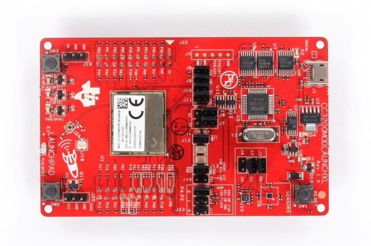
Internet of Things (IoT) enabled devices have become increasingly important as they facilitate seamless communication, automation, and data exchange between devices and systems. To simplify the design process, Texas Instruments (TI) has launched a reference design of a programmable wireless development board CC3200 with built-in Wi-Fi capabilities. The device allows customers to design their own IoT applications easily. The chip integrates all necessary system-level hardware components, such as clocks, Serial Peripheral Interface (SPI) flash, Radio Frequency (RF) switch, and required passive components. The LaunchPad module has programmable user buttons and a Red Green Blue (RGB) Light Emitting Diode (LED), enabling custom applications. It is also equipped with on-board sensors such as temperature and accelerometer sensors via inter-integrated controller (I2C) bus and on-board emulation for debugging purposes.
The reference design is based on the ARM Cortex-M4 40-pin microcontroller unit (MCU) with SimpleLink Wi-Fi and an internet-on-a-chip module solution. The device has Future Technology Devices International (FTDI) based Joint Test Action Group (JTAG) for flashing code on the MCU. Two push buttons and 3 LEDs are interfaced with the microcontroller for user interaction. The module includes universal asynchronous receiver-transmitter (UART) pins, an on-board chip antenna, an accelerometer, a temperature sensor, and I2C pins. The board can be powered through its on-board micro Universal Serial Bus (USB) connector. A Low Dropout Regulator (LDO) on the board supplies 3.3 V to the main MCU and other components. The LaunchPad can be powered either by the USB connection or with external 2xAA/2xAAA batteries.
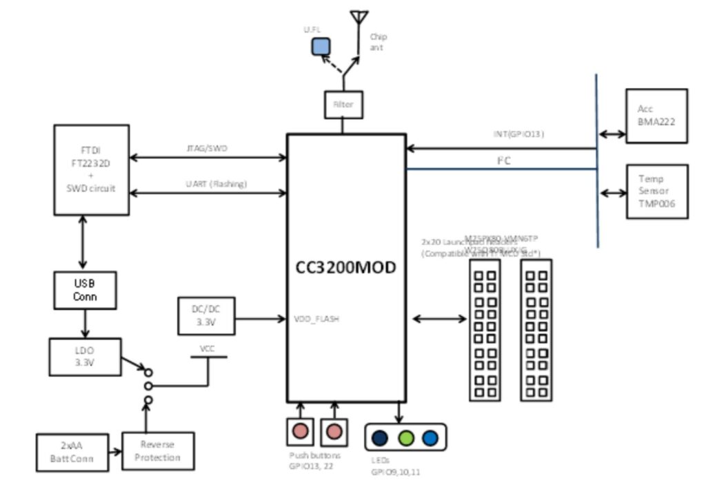
The chip requires an integrated development environment (IDE) that supports the CC3200 device for coding. The development board has two 20-pin stackable headers or BoosterPack headers to connect other peripherals or BoosterPacks to the chip. By utilizing the LaunchPad stackable headers interface, it is possible to expand the module’s functionality when interfacing with other peripherals on existing BoosterPack add-on boards. This enables adding features like graphical displays, audio codec, antenna selection, environmental sensing, and more. The board comes with Radio Frequency (RF) signals routed to the on-board chip antenna by default. For lab testing purposes the module comes up with an on-board ultra-small FL (U. FL) connector to which a compatible cable can be connected.
This reference design has been tested by TI. It comes with BOM, schematics, Gerber file, Printed circuit board (PCB) layout, CAD/CAE symbol, Assembly drawing, Schematic, etc. You can find additional data about the reference design on the company’s website. To read more about this reference design, click here.