


Even though water covers two-thirds of the Earth’s surface, less than 1% of it is fresh and easily accessible for human use. Preventing unnecessary wastage of this limited resource is therefore essential. Several methods are currently employed to address this concern, and one effective approach is to use an electronic or electrical system to prevent storage water tanks from overflowing. This also helps conserve electrical energy by ensuring the pump motor runs only long enough to fill the tank with the correct volume of water.
POC Video Tutorial
Here we describe an electronic system that uses a dedicated water-level sensor to switch off the pump motor as soon as the tank begins to overflow. Unlike many existing systems, this design does not require any modification to the water tank itself. The sensor is instead mounted at the end of the overflow pipe connected to the tank. The author’s prototype, built on a general-purpose PCB, is shown in Fig. 1.
The Technique for Overflow Stopper
The system uses magnetic float sensor FS37A, as shown in Fig. 2. This type of liquid-level sensor uses a float containing a permanent magnet. The float moves up and down along a hollow, sealed plastic stem, following the level of the liquid it floats on, and the magnet inside moves with it. The stem is hermetically sealed and houses a reed switch.
The float’s initial position relative to the reed switch determines whether the sensor is normally closed (N/C) or normally open (N/O). Fig. 3 shows an N/O-type sensor. In this configuration, the reed switch remains open (off) as long as the float rests on the stopper. As the liquid level rises, the float moves upward, bringing the magnet closer to the reed switch. When the magnet reaches the switch, the switch closes due to the magnetic field. Electric current then flows through the reed switch via connecting wires. A relay-control circuit uses this current to energise or de-energise an electromagnetic relay, which in turn switches the pump motor on or off.
To use this sensor effectively within the system, a sensor assembly is constructed to house the sensor. When the assembly is attached to the overflow pipe of a water tank (see Fig. 4), the overflowing water acts on the float, driving it upward.
| S-R latch Truth table | |||||
| S | R | Output (Pin 3) | Comment | T1 Collector Voltage | Relay/Pump Status |
| 1 | 1 | No change | Memory effect | No change | No change |
| 1 | 1 | SET | 0V (approx) | Turned off | |
| 1 | 0 | RESET | +5V (approx) | Turned on | |
| 0 | 0 | Not available | |||
Circuit and Working
Fig. 5 shows the circuit diagram for controlling the relay. Here, a 555 timer (IC2) is configured as a bistable multivibrator (S-R latch). Trigger pin 2 of IC2 serves as the set (S) input, while reset pin 4 functions as the reset (R) input. Transistor T1 acts as a NOT gate, inverting the logic level of the output (pin 3) of the S-R latch. The truth table of the S-R latch is shown in the table.
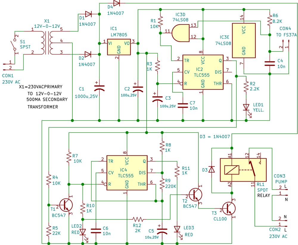
The power supply circuits are self-explanatory. The +12V supply is obtained as an unregulated rectified output from step-down transformer X1 (a 230V to 12V-0-12V, 600mA centre-tapped transformer). Rectification is carried out by two 1N4007 diodes (D1 and D2), with capacitor C1 serving as the input filter. To derive a regulated +5V supply from this unregulated +12V supply, a three-terminal voltage regulator, LM7805 (IC1), is used, while capacitor C2 helps minimise residual ripple.
To understand the functioning of the relay-control circuit, consider a situation in which the tank is not overflowing and there is insufficient stagnant water inside the sensor assembly to drive the float upwards. In such a state, the float rests on the stopper, keeping the reed switch open.
A 2-input TTL AND gate, IC3D (one-fourth of 74LS08), continuously monitors the open or closed status of the reed switch inside the sensor. Of the four 2-input AND gates (IC3A, IC3B, IC3C, and IC3D) available in IC3, only IC3D is used in this system for monitoring.
Once S1 is switched on, the relay-control electronics connect to the +5V supply line. The output of the AND gate at pin 11 goes high (logic 1) because pin 12 is connected to +5V, and pin 13 also receives +5V through R6, since the reed switch remains open. As a result, the S input of the S-R latch goes to logic 1.
The R input of the latch momentarily goes low due to the power-on-reset components R3 and C3. Consequently, the S-R latch at pin 3 of IC2 goes to logic 0. Transistor T1 does not conduct, and the collector of T1 rises to 5V.
The Darlington pair (T2 and T3) then receives sufficient base-drive current from the 5V supply through resistors R7, R10, and R12 and enters a highly conductive state. The high emitter current of T2 flows through the base-emitter junction of T3, forcing T3 into saturation. This draws a large current from the +12V supply through the relay coil, energising the relay and closing its normally open contacts. As a result, the pump motor receives the 230V AC supply through the closed contacts and begins lifting water into the tank.
After a short period, the reset input (R) returns to logic 1 state. With both S and R at logic 1, the latch retains its existing state. Therefore, the relay remains energised, and the pump continues to run.
If the tank begins to overflow, some of the excess water drains out through the bottom holes of the sensor assembly, but sufficient overflow still enters the assembly through the connected pipe to push the float upwards. After a short delay, the reed switch closes due to the magnetic field generated by the float magnet. This pulls pin 13 of the IC3D (74LS08) down to logic 0, corresponding to second line in the truth table.
In this state, the collector voltage of transistor T1 drops towards 0V, cutting off transistors T2 and T3. As a result, the relay becomes de-energised, switching off the pump motor and stopping the overflow. The stagnant water in the sensor assembly then drains out gradually through the bottom holes.
To operate the pump again, S1 must be switched off, then back on to discharge capacitor C3.
An LED blinker built around IC4 (NE555) is configured as an astable multivibrator, with output pin 3 driving LED3 via resistor R11. When T1 does not conduct, pin 4 of IC4 gets +5V, thereby enabling IC4. As a result, LED3 starts blinking and continues to do so as long as T1 remains non-conductive. This indicates that the pump is running. The combination of capacitor C5 and resistors R8 and R9 determines the blinking frequency. Instead of LED3, a small buzzer can be used to provide an aural indication.
Restarting is possible only when the stagnant water level has fallen sufficiently to bring the float back to its initial resting position on the stopper, restoring the reed switch to its open state.
The overflow stopper system requires two separate power supplies: one for the relay-control electronics and another for the relay coil. The control electronics operate on a regulated +5V supply, while the relay requires a +12V supply to ensure reliable operation.
| Parts List |
| Semiconductors: IC1 – LM7805, 5V regulator IC2 – TLC555 timer IC3 (A-E) – 74LS08 quadruple two-input AND gate D-D4 – 1N4007 rectifier diode T1, T2 – BC547 NPN transistor T3 – CL100 NPN transistor LED1, LED2 – 5mm yellow, red LEDs Resistors (all 1/4-watt, ±5% carbon): R1, R4, R7 – 10kΩ R2 – 2.2kΩ R3, R8, R10, R11 – 1kΩ R5 – 22kΩ R6 – 8.2kΩ R9 – 220kΩ R12 – 2kΩ Capacitors: C1 – 1000µF, 25V electrolytic C2, C3 – 100µF, 25V electrolytic C4, C6, C7 – 10nF ceramic disc C5 – 10µF, 25V electrolytic Miscellaneous: CON1-CON4 – 2-pin connector SENSOR – FS37A float sensor S1 – On/off switch RL1 – 12V DPDT relay (PCB mounted) X1 – 230V AC primary to 12V-0-12V AC, 500mA secondary transformer EFY note: Only IC3D and IC3E are used here. |
Construction and Testing
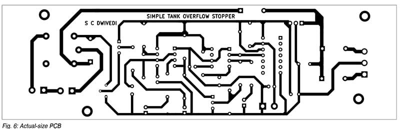
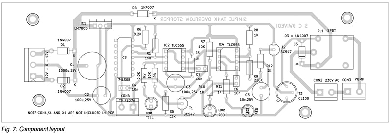
An actual-size, single-side PCB layout for the tank overflow stopper system (Fig. 5) is shown in Fig. 6, along with its component layout in Fig. 7. Once the circuit is assembled on the PCB, it should be enclosed in a suitable cabinet. The footprints for CON1, S1, and the transformer are not included on the PCB; therefore, these components must be mounted externally.
Alternatively, the system can be assembled and tested on three separate Veroboards: one for the power supply unit, one for the relay-driving electronics, and the third for the relay itself. Mounting the relay separately enhances safety because the 230V AC mains enters the PCB through the relay contacts. All three boards, along with the transformer, can be housed in a metal enclosure. Wires from the sensor assembly may be connected to the circuit board through a 2-pin electrical connector.
Standard PVC electrical wires can be used for interconnections and to connect the sensor to the electronics board. Push-type 6mm thimbles are helpful to connect the relay contacts to the pump motor.
Water Level Monitoring and Control Projects
- Stop Tank Overflow With Wireless Water Level Indicator and Controller
- Water Level Indicator Circuit (LED based)
- Water Level Indicator using 7-Segment Display
- Water Tank Overflow Indicator
- Wireless Water Level Monitoring and Pump Control System
- Automatic Water Pump Controller
- Smart Water Meter To Help Control Water Wastage
- Water Level Detection and Alert System Using Arduino
- Ultrasonic Liquid Level Monitoring System Using MATLAB
Arup Kumar Sen is an ex-technical officer at SAIF Bose Institute, Kolkata