


This circuit can be operated by any kind of switch. For example, it can be used in a shop to warn that a customer is waiting, with a micro-switch attached to the shop door. Or you can fix a suitable switch at the front gate to inform that visitors are waiting.
The circuit is built around two ICs and some discrete components. One is CMOS 14-stage ripple-carry binary counter/divider and oscillator CD4060 (IC1) and another is quad 2-input NOR gate CD4001 (IC2).
The sounds are generated by an oscillator built around IC1. The frequency of the oscillator is determined by the values of capacitor C1 (4.7n) and resistor R2 (4.7k) as follows:
Frequency (f) =1/(2.2 R2xC1)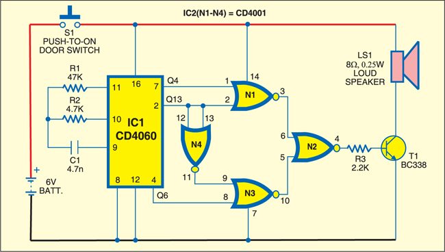

With the values given in the circuit, the clock’s frequency is approximately 20 kHz. This frequency is divided into four stages of binary division before we see it at Q4 output (pin 7) of IC1. Four binary stages are equal to division by 16, so the signal at pin 7 of IC1 has a frequency of 1.25 kHz. This is comfortably within the audio range and makes a suitable basic frequency for the rest of the circuit’s operation.
To obtain a two-tone signal, you require a second frequency. This is picked up from output Q6 at pin 4, which is approximately around 300 Hz. Further along the chain the frequencies drop below the audio range. For example, at Q13 output of IC1, the frequency is approximately 2.44 Hz. This is inaudible, but is useful enough for controlling the two-tone effect. This frequency at Q13 is used here as a control signal.
The two audio signals from pins 7 and 4 are not fed to a pair of NOR gates in IC2 (gates N1 and N3) simultaneously. Gate N1 receives Q13 directly, while gate N3 receives Q13 after it has been inverted by gate N4. Gate N4 has its two inputs wired together so it operates as an inverter (or NOT) gate.
When the control signal Q13 is low, gate N1 passes the 1.25kHz signal and (since the inverted control signal is high) output of gate N3 is held low. But when the control signal is high, the 300Hz signal passes gate N3 and the output of gate N1 is low. The outputs of gates N1 and N3 are fed to gate N2, which acts as a mixer.
In this way transistor T1 receives the two audio signals alternately. Transistor T1 drives the loudspeaker LS1 and produces a two-tone sound. There is no volume control in this circuit. Volume is plentiful with this value of R3 (2.2k), but you can increase the value of R3 to produce a soft tone.
The circuit is intended to operate on 6V, either from a 6V mains plugpack (non-regulated) or a battery pack of four AA cells. Since it takes current only when the switch S1 is pressed, the batteries should last a long time.
Assemble the circuit on a general-purpose PCB and house it in a small plastic box with an aperture cut for the speaker. Use a 40mm miniature speaker, which is easily glued to the panel by its rim.
