


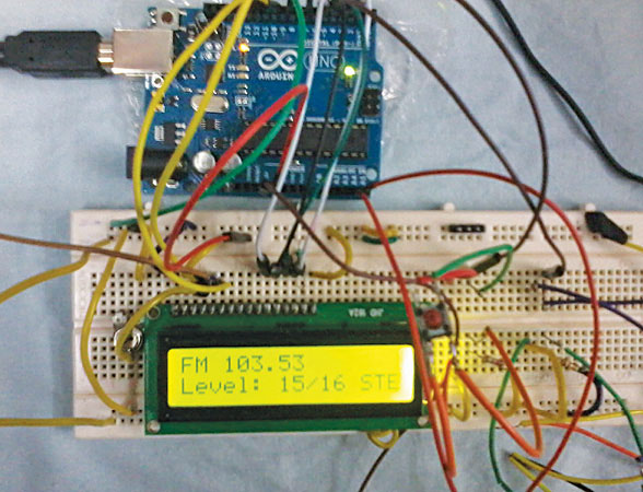
This project is an FM receiver circuit radio based on Philips TEA5767 digital radio-receiver module. The radio receiver uses I2C interface with Arduino UNO development board. The TEA5767 module offers such features as stereo or mono outputs, radio station scanning and signal strength indication. The author’s prototype on a breadboard is shown in Fig. 1.
Circuit and working
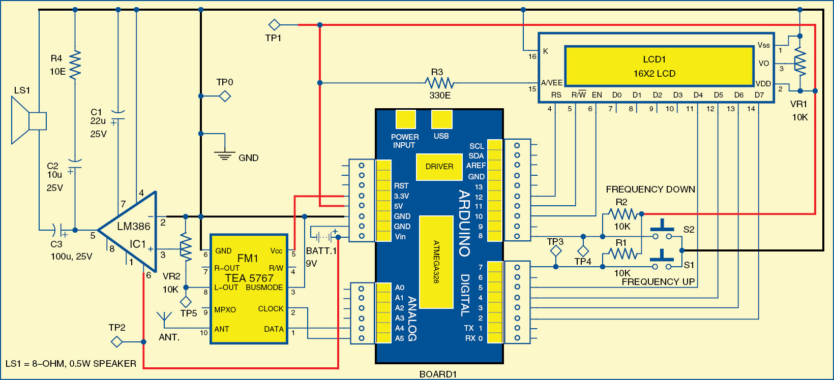
The circuit of the Arduino-based FM receiver, shown in Fig. 2, is built around Arduino UNO board (board1), TEA5767 radio receiver module (FM1), LM386 low-power amplifier (IC1), 16×2 LCD (LCD1) and 8-ohm speaker (LS1).
Arduino UNO board
Arduino is an open source electronics prototyping platform based on flexible, easy-to-use hardware and software. It is intended for artists, designers, hobbyists and anyone interested in creating interactive objects or environments.

Arduino UNO is a board based on ATmega328 microcontroller. It has 14 digital input/output pins, six analogue inputs, a USB connection for programming the on-board microcontroller, power jack, an ICSP header and a reset button. Operation is with a 16MHz crystal oscillator and contains everything needed to support the microcontroller. It is easy to use as the user simply needs to connect it to a computer with a USB cable, or power it with an AC-to-DC adaptor or battery, to get started. The microcontroller on the board is programmed using Arduino programming language and Arduino development environment.
Pins A4 and A5 of the Arduino board are connected to DATA and CLOCK pins of the FM module (FM1), respectively. 10 through 12 pins of the Arduino board are connected to EN, R/W and RS pins of LCD1 while pins 2 through 5 are connected to data pins of the LCD. Pins 7 and 8 of the Arduino board are connected to tactile switches S1 and S2 to increase and decrease FM frequency, respectively.

TEA5767 receiver module
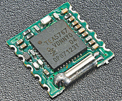
The TEA5767 is a single-chip electronically-tuned FM stereo radio module for low-voltage applications with fully-integrated intermediate frequency (IF) selectivity and demodulation. The TEA5767 module is shown in Fig. 3. Its operating power supply can range from 2.5V to 5V (maximum).
The radio module is completely adjustment-free and requires a minimum of small and low-cost external components. The oscillator in TEA5767 operates with a 32.768kHz or 13MHz external crystal. The module can be configured to operate either in I2C mode or 3-wire bus mode, selectable via BUSMODE pin. In this project, the module is operated in I2C mode by grounding the BUSMODE pin.
The module also provides 4-bit level information via the bus. There is autonomous search tuning function inbuilt in the module along with many more features.
Pins 3 and 6 of TEA5767 module (FM1) are connected to ground. Pins 7 and 8 of FM1 provide outputs for right and left channel, respectively.

LM386 amplifier. The output signals from the module are very low and inaudible, so we need to use an audio-amplifier circuit. Here, for testing purpose, we use low-voltage power amplifier LM386 at the left channel output. Use VR2 to adjust the volume in the speaker. If you want stereo output, you should use another LM386 with the same configuration at the right channel output of the module.
Software program
 The software of fm receiver circuit is written in Arduino programming language. The Arduino UNO is programmed using Arduino IDE software. ATmega328 on Arduino UNO comes with a boot loader that allows you to upload new code to it without the use of external hardware programmer. It communicates using the STK500 protocol. You can also bypass the boot loader and program the microcontroller through ICSP (in circuit serial programming) header, but using boot loader programming is quick and easy. Select the correct board from ‘Tools → Board’ menu in Arduino IDE and burn the program (sketch) through standard USB port in the computer.
The source code for the same is provided with auto-scan function as well as without auto-scan function.
Programming steps
The program for this fm receiver circuit performs the following functions:
1. Initialising the TEA5767 module
2. Writing the data to TEA5767 module
3. Reading the TEA5767 module values
4. Displaying information on the LCD screen
5. Scanning available FM channels
6. Increasing or decreasing the frequency by a unit defined value of particular MHz.
The source program is well commented, which can be seen by opening the file in Arduino software.
Writing data to TEA5767
The useful details about writing the byte and reading the byte can be obtained from page numbers 13 through 16 of the datasheet (Rev.5).
Wire.BeginTransmission(0x60);
This is used to start I2C communication with the TEA5767 module
The address of TEA5767 is 0x60 during writing
The address of TEA5767 is 0x61 during reading
Wire.write(0x00);
This is used to send data to the I2C device byte by byte
The significance of various bytes in TEA5767 is also mentioned on page numbers 13 through16 of its datasheet. The data byte sequence for the write mode is shown in Fig. 4; the remaining detail can be found in the datasheet.
Bitwise operators used for programming the first two bytes of TEA5767 are explained below:
Bitwise operators
& (bitwise and)
| (bitwise or)
^ (bitwise xor)
~ (bitwise not)
<< (bitshift left) >> (bitshift right)
Since structures of the first and the second bytes are different, different bitwise operators are used.
Read mode
In read mode, we have to note the following changes:
1. When a station is found in search mode, as instructed during write operation, the ready flag (RF) in first byte is set to 1. That is, RF=1
2. The values of signal strength level in 4th byte
3. Stereo or mono reception in 3rd byte
For reading the values from TEA5767, the following method is used in the code by creating a buffer as follows:
Buffer [i]= Wire.read ();
Wire.read (); is used to read the values of all the five bytes in Read mode.
Displaying values on LCD screen
The task of displaying values is performed by reading the values of bytes of the TEA5767 in read mode.
1. The available frequency is displayed on LCD screen by reading first byte stored in buffer(0); this value is stored in buffer during read operation
2. If search mode is high, a scan is displayed on the screen
3. The signal strength is stored in the 4th byte which can be obtained by reading the buffer(3)
4. The reception type is displayed on screen by reading the buffer(3).

Download PCB and component layout PDFs: click here
Download source code for the fm receiver circuit: click here
Searching/changing the frequency. Switches S1 and S2 are used to change the station/channel search or switch to auto-scan mode. Search-up or search-down operation depends on the switch pressed. The 7th bit of 3rd byte in write operation is for search-up or search-down operation. The implementation of these operations has been included in the code.
R1 and R2 are pull-up resistors connected at digital pins 7 and 8 of Arduino board, respectively.
Construction and testing
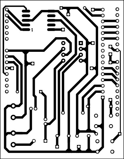
An actual-size (Arduino shield type), single-side PCB for Arduino FM receiver circuit is shown in Fig. 5 and its component layout in Fig. 6. Assemble the components on the recommended PCB to avoid assembly errors. Double check for any overlooked error. TEA5767 is to be mounted on solder-side of the PCB.
A 75cm (wavelength/4) hookup wire antenna should be connected at pin 10 of the TEA5767 module.
Switch on the fm receiver circuit and use switch S1 or S2 to change frequency. Pressing S1 momentarily increases the frequency and S2 decreases the frequency. Long pressing of any of the two switches will enable auto scanning.
LCD1 shows the selected frequency, signal strength and whether the sound is mono or stereo.
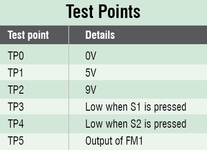
To test the fm receiver circuit for proper functioning, first verify the correct voltages at various points as given in the test points table.
The author is a final-year student of B.Tech (ECE) from Truba Institute of Engineering & IT, Bhopal (MP)


link for download source code is not working
Please check again. From our side the link is working.
Hello,
Can we use 5767 for tuning to FM stations in India!!
Thanks
Yes, as per datasheet this TEA5767 works between 76Mhz to 108 Mhz.
what about the volume control?? can it be done??
can you provide the kit too…because am unable to get all the components
@ Shiva Samrat : Kit isn’t available for this project. But you may visit kitsNspares.com where you can get wide range of DIY projects with all required components and PCB.
What about turning it into an airtraffic receiver. Does the TEA5767 go above 108MHz?
The datasheet does no say that but does anyone tried it?
It would be great if it could be told to tune from 108-118MHz in 50kHz steps (i a not shure about this channel spacing).
I hava an analog FM receiver modfied for this but would it be great to have a digital one?
If it’s not possible with this chip then what else to use? I think it’s a great project that is not yet done (i found none in google)
source code cannot be opened in arduino sketch. Please send the correct arduino sketches
plz i need prg for start plaquet arduino for my project
Kindly elaborate your query.
i can only hear a static noise. no sign of fm transmission
Is there a video for this project?
Can I use RDA5807M instead of tea 5767 module with the same code or need any modifications?
We have not checked with RDA5807M. So, we cannot comment on that right now.