


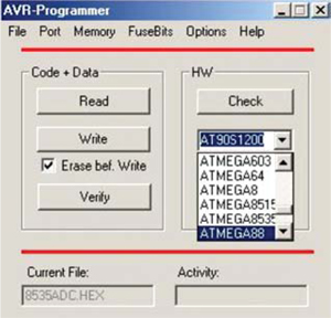
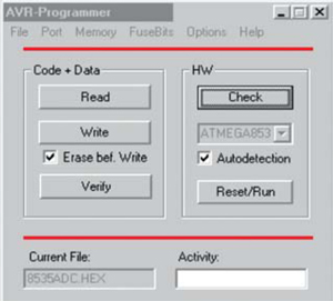
Programming the chip
The AVR source code file with ‘.asm’ extension can be written using either the EDIT, Wordpad or notebook programs.
As with all microprocessor or micro controller programs, for the source code, one has to enter the program by mnemonics and assembler directives and then convert the same into a code list for the program. (Directives are assembler commands used to control the input, output and data allocation of the assembler. These are, however, not translated into op-codes directly.) This is done using the cross-assembler software ‘avrasm.exe.’

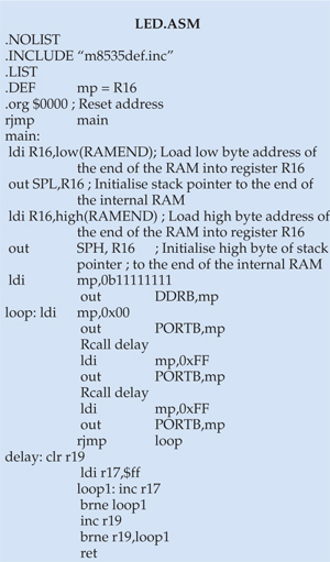
To describe the modus of writing of an Assembly language program, a simple program (LED.ASM) for AVR processors is given below:
This program helps you understand:
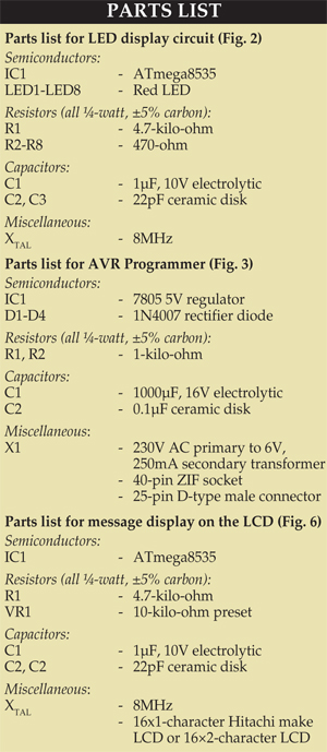
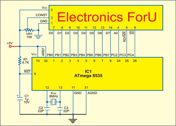
1. Access to the output port (here port B, where LEDs are connected)
2. The different parts of a typical assembler program
3. Different conventions like use of semicolon, upper-/lower-case letters, etc
Explanatory notes for LED.ASM
1. In Assembly language, all the text on a line after a semicolon (;) is treated by the cross-assembler as comments and it does not use it for code formation.
2. Including the m8535def.inc processor-specific file in Assembly program means all the I/O register names, I/O register bit names, etc appearing in the datasheet can be used. Failure to include this file may result in a number of error messages. Ensure that this file is placed in the same directory as your source code file (LED.asm in this case). Else, give complete path for the m8535def.inc file.
3. Following conventions havebeen used in the program:
(a) Words in upper-case letters are used for command directive words of the Assembly language or predefined ports of the processor.
(b) Mnemonic words are written in lower case.
4. LIST directive turns on the listing output if it had been previously turned off. Similarly, NOLIST directive, if used, will turn off the listing output.
5. DEF directive is used to define a text-substitution label for a string. A label/name is easy to remember. Here, register R16 is replaced with ‘mp’ name. Thus whenever ‘mp’ is encountered in the source code, it will be automatically replaced with ‘R16.’
6. ‘.org $0000’ defines the reset address. When power is swit
ched on, the program starts from this location. A restart from the reset address can be activated by resetting the respective hardware pin of the chip (pin 9) or upon watchdog timer reaching its zero count. A relative jump command (rjump) at this reset location directs the program execution to label (main)—as long as the label is within 2k locations from the reset address (0000). Incidentally, ‘rjmp main’ is the first code-generating instruction.
7. It is essential to set up the stack pointer before being able to call any subroutine, since stack is required for saving the return address, where the next program execution is to start from. The program lines starting with ‘ldi R16,low(RAMEND)’ and ending with ‘out SPH, R16’ do just that.
8. The ‘ldi mp, 0b11111111’ and ‘out DDRB, mp’ lines set port-B pins as the output. The first line, interpreted as ‘load immediate (ldi) into register ‘mp’’, loads binary value ‘11111111’ into the ‘mp’ register. The second line transfers the contents of ‘mp’ (11111111) to the data direction register of port B (DDRB). DDRB is already defined in the m8535def.inc file. (If you want to set port-B pins as input, load binary ‘00000000’ into ‘mp’ and output it to DDRB.) Incidentally, ‘0b’ precedes a binary number. Similarly ‘0x’ precedes a hex number. Numbers without these prefixes denote decimal numbers by default. Hence you may replace ‘0b11111111’ with either ‘0xFF’ or simply ‘255’ to achieve the same results.
9. The rest of the program starting at label ‘loop:’ and ending with ‘rjmp loop’ achieves switching on and off of the LEDs with a delay. The delay subroutine starting at label ‘delay:’ and ending with return instruction ‘ret’ is called from within the loop.
Initially, ‘mp’ is loaded with hex value ‘00’ and output through port-B pins, making them low. Since the cathodes of all the eight LEDs are connected to these port pins via current-limiting resistors, the LEDs light up. Thereafter, the delay subroutine (Rcall delay) is called and ‘mp’ is loaded with hex value ‘FF’ and transferred to the port-B output to turn off the LEDs. The loop is repeated as long as the power is switched on.
10. The internal R-C clock of ATmega8535 is 1 MHz by default. In the absence of ‘Rcall delay’ instruction, each of ‘ldi’ and ‘out’ instructions requires 1000 ns, while ‘rjmp’ instruction requires 2000 ns. Thus loop execution would take 4000 ns. This amounts to LED switching rate of 250 kHz.
Introduction of delay between switching on and off reduces this frequency to around 0.5 Hz by decrementing registers ‘r19’ and ‘r17’ from ‘255’ to ‘0,’ thereby making the elapsed time slower by 256×256 (which works out to around 0.5Hz rate).
After assembling the LED.asm source file, the program will have eight words. The LED.LST file stores the result of the assembly process in the form of a listing.

Great Work!
This information help me a lot!