


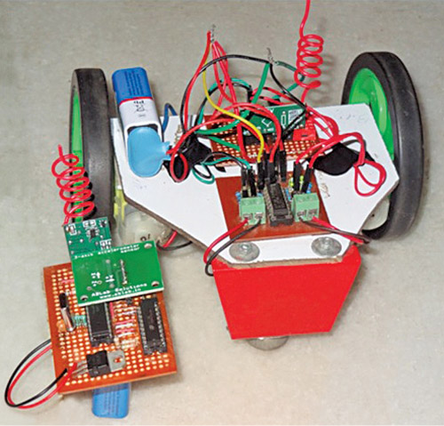
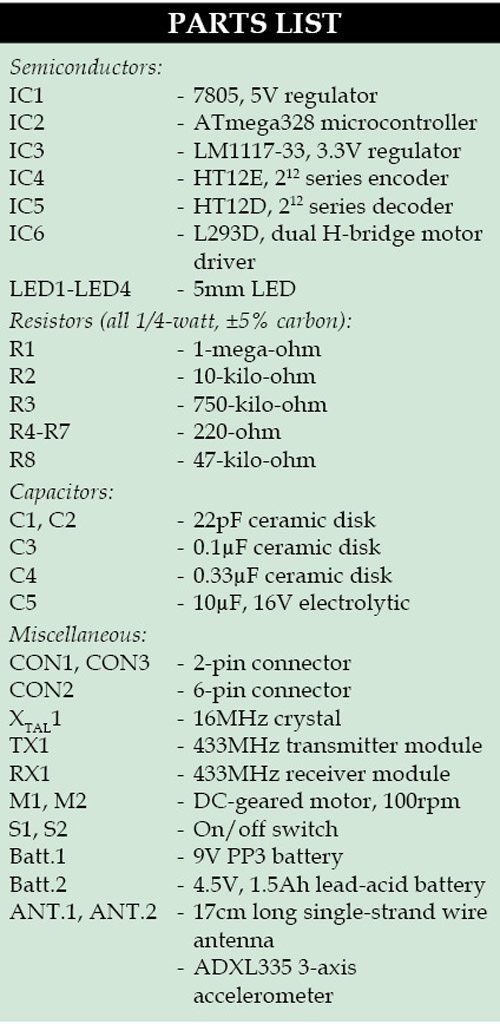
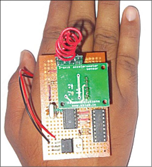
 In this wireless gesture controlled robot project we are going to control a robot using hand gestures. This is an easy, user-friendly way to interact with robotic systems and robots. An accelerometer is used to detect the tilting position of your hand, and a microcontroller gets different analogue values and generates command signals to control the robot. This concept can be implemented in a robotic arm used for welding or handling hazardous materials, such as in nuclear plants. The author’s prototype is shown below.
Circuit and working
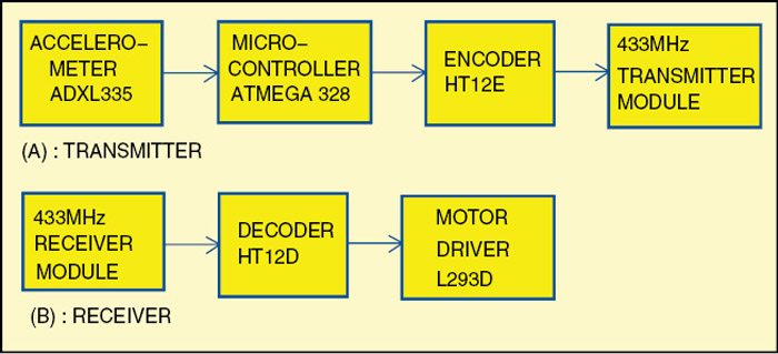
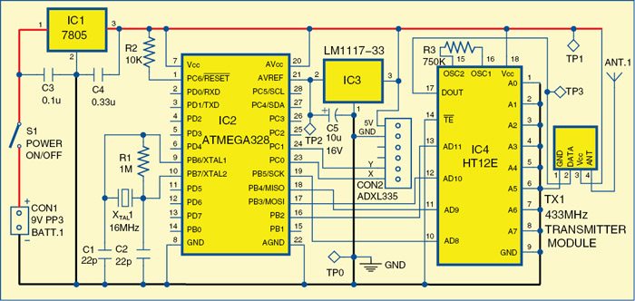
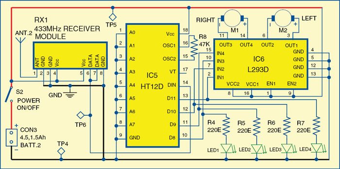
The block diagram of the wireless gesture-controlled robot is shown in Fig. 2. The circuit diagram of the transmitter section of the wireless gesture-controlled robot is shown in Fig. 3 and of the receiver section in Fig. 4.
ATmega328
ATmega328 is a single-chip microcontroller from Atmel and belongs to the mega AVR series. The Atmel 8-bit AVR RISC based microcontroller combines 32kB ISP flash memory with read-while-write capabilities, 1kB EEPROM, 2kB SRAM, 23 general-purpose I/O lines, 32 general-purpose working registers, three flexible timers/counters with compare modes, internal and external interrupts, serial programmable USART, a byte-oriented 2-wire serial interface, SPI serial port, 10-bit A/D converter, programmable watch-dog timer with an internal oscillator and five software-selectable power-saving modes.

 The device operates between 1.8 and 5.5 volts. It achieves throughputs approaching one MIPS per MHz. An alternative to ATmega328 is ATmega328p.
ADXL335
This is a complete three-axis acceleration measurement system. ADXL335 has a minimum measurement range of ±3g. It contains a poly-silicon-surface micro-machined sensor and signal-conditioning circuitry to implement open-loop acceleration measurement architecture. Output signals are analogue voltages that are proportional to acceleration. The accelerometer can measure the static acceleration of gravity in tilt-sensing applications as well as dynamic acceleration resulting from motion, shock or vibration.

The sensor is a poly-silicon-surface micro-machined structure built on top of a silicon wafer. Poly-silicon springs suspend the structure over the surface of the wafer and provide resistance against acceleration forces. Deflection of the structure is measured using a differential capacitor that consists of independent fixed plates and plates attached to the moving mass.
Fixed plates are driven by 180° out-of-phase square waves. Acceleration deflects the moving mass and unbalances the differential capacitor, resulting in a sensor output whose amplitude is proportional to acceleration. Phase-sensitive demodulation techniques are then used to determine the magnitude and direction of the acceleration.
L293D
This is a 16-pin DIP package motor driver IC (IC6) having four input pins and four output pins. All four input pins are connected to output pins of the decoder IC (IC5) and the four output pins are connected to DC motors of the robot. Enable pins are used to enable input/output pins on both sides of IC6.
Encoder (HT12E) and decoder (HT12D) ICs
The 212 encoders are a series of CMOS LSIs for remote-control system applications. These are capable of encoding information that consists of N address bits and 12 N data bits. Each address/data input can be set to one of two logic states. Programmed addresses/data are transmitted together with header bits via an RF or infra-red transmission medium upon receipt of a trigger signal. The capability to select a TE trigger on HT12E or a data (DIN) trigger on HT12D decoder further enhances the application flexibility of 212 series of encoders. The HT12D also provides a 38kHz carrier for infra-red systems.
Download the PCB and component layout PDFs: click here
Download the source code: click here
Transmitter
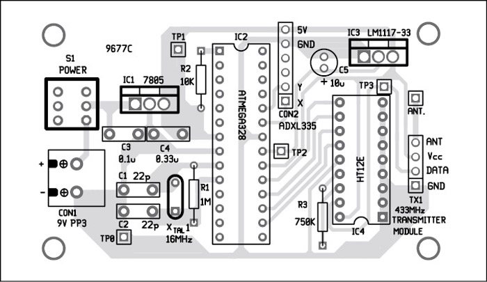
The transmitter consists of ATmega328 microcontroller (IC2), ADXL335 accelerometer, HT12E encoder (IC4) and 433MHz RF transmitter module (TX1). In this circuit, two analogue outputs from ADXL335 pins (x, y) are connected with input pins (23, 24) of the microcontroller. Analogue signals are converted to digital signals through the microcontroller. Digital outputs from pins 16, 17, 18 and 19 of the microcontroller are directly sent to pins 13, 12, 11 and 10 of encoder IC4. This data is encoded and transmitted via RF module TX1.
Receiver
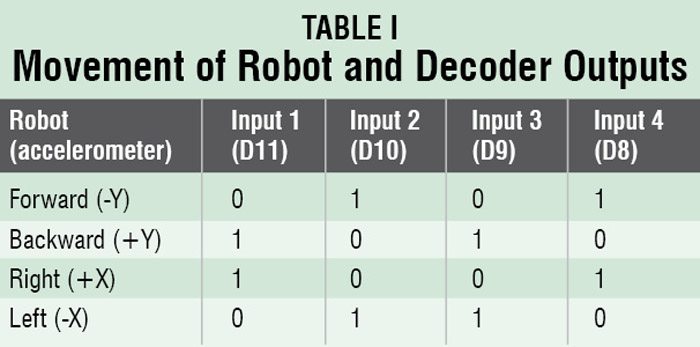
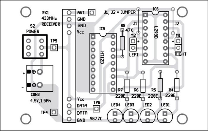
The receiver part consists of 433MHz RF receiver module (RX1), HT12D decoder (IC5) and L293D motor driver (IC6) to run the motors. Here, receiver module RX1 receives the transmitted signal, which is decoded by decoder IC to get the same digital outputs. Four outputs of IC6 drive two motors. The robot moves as per tilt direction of the accelerometer in the transmitter. The direction of the robot movement is as per logic listed in Table I.
Software program
The software program is written in Arduino programming language. We programmed a fresh ATmega328 microcontroller with the help of Arduino IDE 1.0.5 and an Arduino Uno board.
First, we have to load bootloader code into the microcontroller. For that, we used Arduino Uno for in-system programming (ISP) given in the IDE, by selecting File → Examples → Arduino ISP. Once the bootloader is uploaded into the microcontroller, gesture.ino code of this project can be uploaded.
Construction and testing
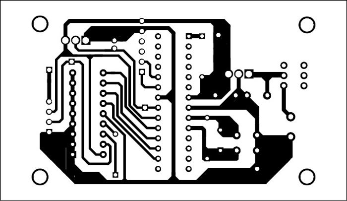
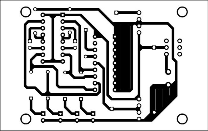
An actual-size, single-side PCB layout of the transmitter circuit is shown in Fig. 5 and its component layout in Fig. 6. An actual-size, single-side PCB layout of the receiver circuit is shown in Fig. 7 and its component layout in Fig. 8.
The transmitter section can be held in your palm or on the other side (refer Fig. 9). The receiver module is mounted on the robot.
Mount all components on the PCBs shown here to minimise assembly errors. Fix the receiver PCB and 4.5V battery on the chassis of the robot. Fix two motors, along with wheels, at the rear side of the robot and a castor wheel on the front. After uploading the main code into the microcontroller, remove it from the Arduino Uno board and insert it into the populated transmitter PCB.
Now, switch-on the power supplies in the transmitter as well as receiver circuits. Attach the transmitter circuit to your hand and move your hand forwards, backwards and sideways. Directions of the robot movement are given in Table I. The robot will stop if you keep your palm horizontal, parallel to the Earth’s surface.
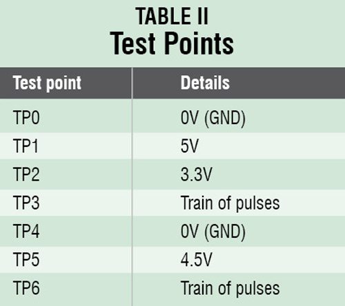
For troubleshooting, first verify that voltages at various test points are as per Table II.
Aquib Javed Khan is pursuing B.Tech from Orissa Engineering College, Bhubaneswar. He is interested in mechatronics systems


I want source code of this project can you please mail me on my mail id [email protected]
Dear Amruta Patole,
The source code is already available within the article. Please check for “Download source code”.
project is not working…plzz help!!
Could you please elaborate your query?
i’d tested the circuit it looks fine and followed each and every step correctly… but when i burn the code its not working…
We are making Accelerometer Based Gesture Controlled Robot ……….so can you suggest a good and simple application of this robot for its extension
HI..
My name is vimal savani
I make hand gesture controlled robot.
There is one problem that is when i tilt accelerometer then robot does not change direction..and not move.. i use here adxl335 accelerometer. So pls.. help me.
Hello brother,
Nice to see you in such forums. I was thinking that I was the only one savani who is active.
shall we implement this project to wireless guesture controlled robotic arm
what is budget of this project???????????
Can you please upload the file of the code
The source code is present on the third page of article.
no its not available in the third page.
Sir in the code the output pins are defined as 10,11,12,13.
But we are using pin nos 16,17,18,19 as output pins .
How????????
When we write in a arduino ide it is 10,11,12,13 but in atmag328 pin 16,17,18,19 after make circuit
sir table 1 has output pins as D11,10,9,8, but in the program it is pin 13,12,11,10.
Also sir tell me about the burning of the microcontroller.
10,11,12,13 is data pin of ht12e
#define FD 16
#define BD 17
#define LD 18
#define RD 19
#define m11 3
#define m12 4
#define m21 5
#define m22 6
void forward()
{
digitalWrite(m11, HIGH);
digitalWrite(m12, LOW);
digitalWrite(m21, HIGH);
digitalWrite(m22, LOW);
}
void backward()
{
digitalWrite(m11, LOW);
digitalWrite(m12, HIGH);
digitalWrite(m21, LOW);
digitalWrite(m22, HIGH);
}
void left()
{
digitalWrite(m11, HIGH);
digitalWrite(m12, LOW);
digitalWrite(m21, LOW);
digitalWrite(m22, LOW);
}
void right()
{
digitalWrite(m11, LOW);
digitalWrite(m12, LOW);
digitalWrite(m21, HIGH);
digitalWrite(m22, LOW);
}
void Stop()
{
digitalWrite(m11, LOW);
digitalWrite(m12, LOW);
digitalWrite(m21, LOW);
digitalWrite(m22, LOW);
}
void setup()
{
pinMode(FD, INPUT);
pinMode(BD, INPUT);
pinMode(LD, INPUT);
pinMode(RD, INPUT);
pinMode(m11, OUTPUT);
pinMode(m12, OUTPUT);
pinMode(m21, OUTPUT);
pinMode(m22, OUTPUT);
}
void loop()
{
int temp1=digitalRead(FD);
int temp2=digitalRead(BD);
int temp3=digitalRead(LD);
int temp4=digitalRead(RD);
if(temp1==1 && temp2==0 && temp3==0 && temp4==0)
backward();
else if(temp1==0 && temp2==1 && temp3==0 && temp4==0)
forward();
else if(temp1==0 && temp2==0 && temp3==1 && temp4==0)
left();
else if(temp1==0 && temp2==0 && temp3==0 && temp4==1)
right();
else
Stop();
}
Kindly elaborate your query.
Please us how to do this. Because this is Our design project (THESIS) Thanks. ? ill Wait for the reply
Hi Rea, all the information is present within the article itself.
Here TP6 in receiver circuit is train of pulses. How may i draw the TP6 in eagle cad? and how may i create train of pulses in circuit
there is no source inur bio page i had gone through download source code link but there is no source code
Download source code: http://efymag.com/admin/issuepdf/Wireles_gesture_controlled_robot.rar
plz mail me sorce code i want to complete my project
What is your budget to finish this project
Loved it but can u help me make without adrino
I am going to do this project please send me the source code to my mail.. I tried to download from the Link you provided but file is not opening after download.. plss send me the source code for my mail..
[email protected]
Please send me bootloader code and ino code
Will You Please Guide For The Steps To Burn The Program On ATMEGA IC
4.5 volt battry is not there so we used 9 volt
hii did your project worked with 9v battery
I can use as a battery × 3 if use hw 9v the device may damage
what is the use of LM117-33 IC in this project?
LM1117-33 IC
I have successfully did this project, Thank you from the bottom of my heart Aquib Sir, and EFY team ???
You are most welcome.
Hi Karanparve….can i have your mail id or phone number,i want to discuss something about the project
reply asap
Sir can u plz provide code for Arduino based hand gesture control chair..??
Hello Sir the file of component layout is damaged can you provide another file ([email protected]).
reply asap
Thank you.
Thank You Arpit,
We have updated the files, you can now download the Component layout for this article.
Sir in receiver ckt vcc and ground both are shorted what is the problem sir please tell me
Sir can we use atmega328p microcontroller instead of atmega328 microcontroller