


Automation systems are increasing in day to day life. Applications like home and industrial automation reduce man power while increasing the efficiency. Here in this restaurant menu ordering system that lets you automate menu for ordering food in restaurants.
In these modern days the number of restaurants are increasing. They also require very fast processing for serving food to the customers. With the increasing number of customers, it would require more man power, since the current situation has become hectic for the restaurants. Also changes in the hardcopy of the menu can’t happen.
Using simple components and programming techniques, an automation system was proposed.

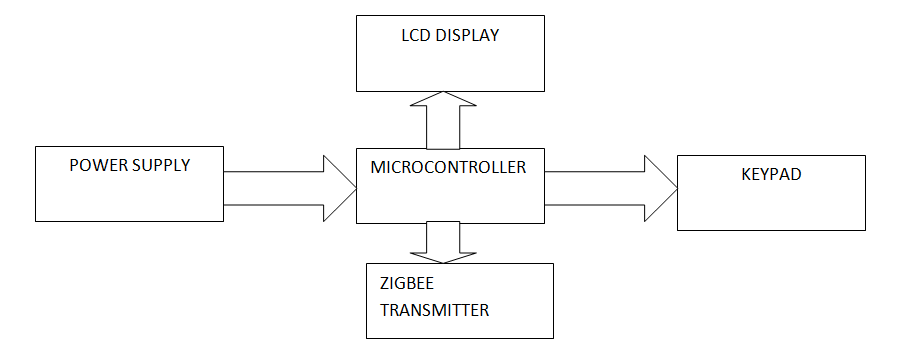
Block Diagram:
SOFTWARE AND HARDWARE TOOLS:
Software Tools:
1. AVR Studio.
2. PROGISP.
3. PROTEUS.
Hardware Tools:
1. Microcontroller.
2. LCD
3. Key pad/touch panel
4. ZIGBEE

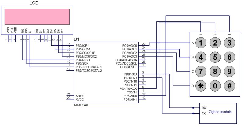
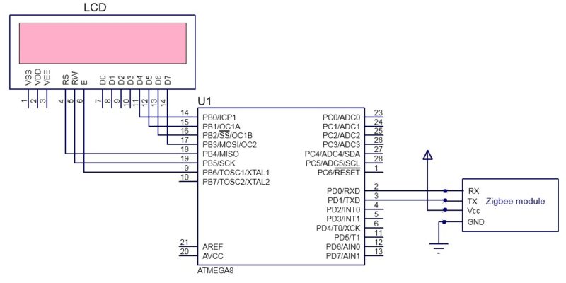
Schematic Diagram:
Circuit Operation:
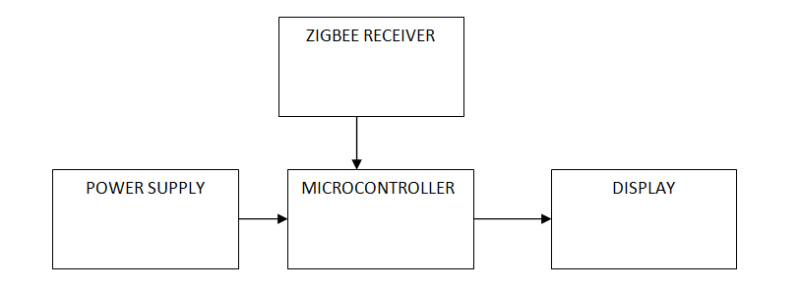
Restaurant menu ordering system consists of a transmitter and a receiver section.
Atemga8 is the AVR microcontroller used for processing the data. The above circuit does not show any clock or reset circuit. For normal operation of the controller reset should be connected to high logic.
Vcc and ground should also be connected to the circuit, which are not shown in the above circuit. It has two ground pins (pin 8 &pin 22). Vcc is connected to 5V and a Vcc is used for A/D conversion. Below is the image showing reset and power connections to the controller.
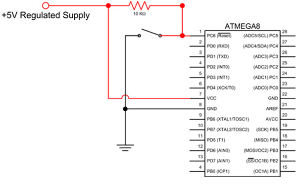
No need of external crystal, it can work with internal oscillator of 8MHz.
Transmitter Section:
The transmitter section, placed at the customer’s table, is in charge of menu selection and order transmission.
- Keypad: The 4×3 keypad allows users to choose menu items. The rows connect to PORT C and the columns to PORT D of the microcontroller.
- Zigbee Transmitter: The microcontroller’s transmitter pin is connected to the Zigbee module’s transmitter, which sends selected orders to the kitchen.
- LCD: LCD Displays selected menu items in 4- bit mode for efficiency.
Receiver Section:
• The receiver section is connected in the kitchen. The order placed by the customer is received by the Zigbee receiver. In real one can form a Zigbee network in which single receiver is used to receive data from different transmitters.
• Thus received data is decoded and is displayed on the LCD .
Working Process:
• The menu is displayed on the LCD .
• User should press the corresponding number of the selected item from the display.
• The project code is provided below. It is written in such a way that one can select 3 items at a time. In real time one can use EEPROM of the microcontroller to store the menu.
• Items are selected using keypad provided. For example in order to select “1. Ice cream” press 1 one from the keypad. Similarly select your items and press ‘#’ .
• Pressing ‘#’ will transmit the order to the receiver.
[stextbox id=”grey”]
Code: /*
* automation_of_restaurant_menu_ordering.c
*
* Created: 6/16/2016 11:40:10 AM
* Author: Anusha
*/
#include <util/delay.h>
#include <avr/io.h>
#define Rows PORTC //Pc0,pc1,pc2,pc3
#define Columns PIND //PD4,PD5,PD6
unsigned char upperNibble, keyCode, keyPressed,k,c[6];
char press_key()
{
unsigned char i;
DDRC = 0x0f;
PORTC=0x0f;
PORTD = 0xf0;
k=1;
while(k==1)
{
upperNibble = 0xff;
for(i=0; i<4; i++)
{
_delay_ms(1);
Rows = ~(0x01 << i);
_delay_ms(1);
upperNibble = Columns| 0x0f;
if (upperNibble != 0xff)
{
_delay_ms(20); //key debouncing delay
upperNibble = Columns | 0x0f;
if(upperNibble == 0xff) goto OUT;
keyCode = (upperNibble & 0xf0) | (0x0f & ~(0x01 << i));
while (upperNibble != 0xff)
upperNibble = Columns | 0x0f;
_delay_ms(20); //key debouncing delay
switch (keyCode)
{
case (0xee): keyPressed = ‘1’;k=0;
break;
case (0xed): keyPressed = ‘4’;k=0;
break;
case (0xeb): keyPressed = ‘7’;k=0;
break;
case (0xe7): keyPressed = ‘*’;k=0;
break;
case (0xde): keyPressed = ‘2’;k=0;
break;
case (0xdd): keyPressed = ‘5’;k=0;
break;
case (0xdb): keyPressed = ‘8’;k=0;
break;
case (0xd7): keyPressed = ‘0’;k=0;
break;
case (0xbe): keyPressed = ‘3’;k=0;
break;
case (0xbd): keyPressed = ‘6’;k=0;
break;
case (0xbb): keyPressed = ‘9’;k=0;
break;
case (0xb7): keyPressed = ‘#’;k=0;
break;
case (0x7e): keyPressed = ‘/’;k=0;
break;
case (0x7d): keyPressed = ‘X’;k=0;
break;
case (0x7b): keyPressed = ‘-‘;k=0;
break;
case (0x77): keyPressed = ‘+’;k=0;
break;
default : keyPressed = ‘X’;k=0;
}
OUT:;
}
}
}
return keyPressed;
}
void uart_init()
{
UCSRC=(1<<URSEL)|(1<<UCSZ1)|(1<<UCSZ0);
UCSRB=(1<<RXEN)|(1<<TXEN);
UBRRL=0x33; // baud rate(51 for 9600)
}
void tx_data(unsigned char c)
{
UDR=c;
while(!(UCSRA & (1<<TXC)));
UCSRA=(1<<TXC);
}
unsigned char rx_data()
{
while ( !(UCSRA & (1<<RXC)) );
UCSRA=(0<<RXC);
return UDR;
}
void Tx_String(unsigned char *str)
{
while(*str)
{
tx_data(*str);
str++;
_delay_ms(100);
}
}
int main(void)
{
uart_init();
unsigned char x,y[4];
int i,j=0;
_delay_ms(100);
while(1)
{
x=press_key();
if((x)!=’#’)
{
y[j]=x;
++j;
}
else if(x==’#’)
{
for (i=0;i<3;i++)
tx_data(y[i]);
_delay_ms(10);
}
}
}
[/stextbox]
Future Enhancements and System Expansion
- Order Limitations: Currently, the system only allows for the selection of three goods per order. For larger orders, more memory (such as EEPROM) can be used to hold the menu and order information.
- Scalability of the Zigbee Network: The system supports numerous transmitters that link to a single Zigbee receiver, allowing a network of tables to place orders at the same time.
- Customization: The system can be modified to support touch panels or more powerful microcontrollers, enhancing functionality and user experience.
- Efficient Ordering: This method dramatically decreases the need for manual order taking, allowing employees to focus on order preparation and improving the overall client experience.
- Expansion Options: The design might be expanded to include payment processing or integration with restaurant management software to provide a completely automated experience.
Download source code: click here
Written by Anusha V From electronicshub.org
This article was first published on 22 June 2016, and recently updated on 30 October 2024.

Very good project indeed. Thanks for sharing. It will create more new ideas about the project.
Cool project, thanks you so much…
I will work on this for my project.
Hi Anusha! Sometimes I wonder how long did it took you to work on this project for coding as I made some necessary changes on Zigbee receiver side for LCD with Beep + showing which remote # No. it was transmitted from and that accordingly on LCD with list of orders Table# no. wise 🙂 keep it up
Hello hiren can you please help me out with the code you used for your modifications of showing table number. please
Hello can you please send me the code which includes table no??
Hii bro ,, can u pls send me project detail with circuit diagram ,coding pls pls
[email protected]
Hello Hiren, thanx for everything. Can u please help me with your source code both for transmitter and receiver side becuse i have been working on this project but its not working.
You can reach me at [email protected]
Thanks alot.
Hello Hiren, can you help me for this project. I am not understand this project properly. Can you provide me the proper circuit diagram with source code. [email protected]
Hi did you try out the project
yup
Hii can u pls help me with the circuit diagram
My mail id is [email protected]
If you get wht u needed can u plzz send this to me
[email protected]
i work on this project but the something wrong in my coding if you have any code of information about this project plz share on this mail [email protected]
A very nice project. How much does the whole project cost
could you please send the code for the receiver at [email protected]
The code is already present within the article.
is it common for both transmitter and receiver?
Can this project be simulated
Can i use the same code on 8051 instead of that microcontroller
No. 8051 and Atmega8 are different microcontrollers and will not work.
hii anusha …this code is not work properly plsss send me proper code…in this code doesnt initialize ..so help me pllsss
haii anusha…
i wanna implement this project plz send me source code for interfacing zigbee module for tx and rx..
haii…
can we connect the rx nd tx of atmega8/atmega16 directly to the xbee module with out using max232. i am confusing as the controller is 5v and xbee is 3.3v can we connect directly iam scared of xbee module may be burn.
can i have code for this project???
The source code is present within the article itself.
Can i have the pattern of the pcb?
Everything is very open with a clear description of the
issues. It was really informative. Your site is extremely helpful.
Thank you for your feedback.
WHAT A BRILLIANT IDEA CAME TO THE WORLD .THIS IS BEAUTIFUL PROJECT ,IT”S SO HELPFUL VERY SIMPLE AND MAKING WORK EASIER.
Thank you for your feedback.
could you please send the code for the receiver
Or it’s same for receiver also
If it’s different plz send at [email protected]
could you please send the code for the receiver at [email protected]
How to implement this project using arduino
is it easy to get the output or any complexity.can you give a over view on how to implement this project very.
[email protected]
please help me with the code that is used for table selection
anusha, plz share to us the specification/description of the project components used
Can u send the proper code on [email protected]
Ty
Hi, this code is not working properly. So, could u please send me complete code on [email protected] .thank you.
Hello Anusha!
Can I use the same code stated above with both transmitter and receiver sides?
And also, can I have a circuit diagram of the clock and reset circuit. If possible, can I also have the PCB layout of all circuits? Kindly send it to my email [email protected]. It will be of great help. Thank you so much!
how can i buy the parts related to the project
superb..could you please send me the details to [email protected]
hello sir
can this project be manufacture by using RF technology instead of zigbee.
please contact me at [email protected]
how to implement this project by using arudino and plz send the code
[email protected]
Plz give me information of interfacing between microcontroller and ZigBee module and which type of ZigBee module is used and their frequency?
This is a very good idea. Please send the proper code for this to the below mail Id
Hii bro ,, can u pls send me project detail with circuit diagram ,with all code plz,,,plz,,
send to me : [email protected]
if sapos i want this project hotel ordaring system
how much cost this project
hey what is the estimation cost for such a project
Hii..nyc project but i want to know the circuit diag nd all..i want to make i..can u send me at this email..
[email protected]
Hi Nikhil, You can get full detail about the circuit in the article itself.
Which basic components are used in this project?
If resister then what is value of resister
‘UCSRC’ was not declared in this scope, please help
If you see that after uploading that shows that you do upload with wrong board setting in the Arduino IDE. So, all you need to do is to check the tools in the IDE and then select the Atmega8 as the board provided you are using Arduino board with the Atmega8. then reupload the code. it will not displace such error again.
Thanks.
can i get the full project
This is the full project.
can you please send me source code for both for transmitter and receiver side because i don`t know where is the break. my id [email protected]
hello..
Anyone send me the project details including circuit diagram and source code for both side. My id [email protected]
Hi, the source code is present at the end of the article.
Please can you provide me the demo video this project and details of hardware tools.