


 This PC based stepper motor controller is perhaps the cheapest, smallest and simplest. A pair of H-bridges with a software program written in ‘C++’ is used to control the bipolar stepper motor with a step resolution of 18 degree per pulse.
The PC based stepper motor controller is a combination of driver and switching circuits. The driver is the actual circuit that drives the stepper motor and the switching circuit decides how the motor should be driven. So, it is basically the switching circuit that controls the motor. The transistors (T1 through T8) act as switches. The switching of these transistors is controlled by the software via data pins D0 through D7.
You can control three parameters of the stepper motor: speed, direction and number of steps. To vary the speed of the motor, you have to vary the pulse repetition frequency (PRF). To change the direction of the motor, you have to change the sequence of pulses applied to its coils. By limiting the number of applied pulses, you can restrict the motor to complete the desired number of steps.

Specifications of the stepper motor
Stepper motors of various ratings/specifications are available in the market for different applications. Here, the stepper motor is taken from an 8.9cm (3.5-inch) floppy drive. It’s a bipolar stepper motor rated at 5V DC with step resolution of 18o per pulse. The motor has two coils inside and four terminals (colour-coded, but not always) for external connections. Stepper motors rated at 5V and up to 1 ampere of current and different step size (e.g., 1.8º per pulse) may also be used with this circuit and control software.
Circuit description
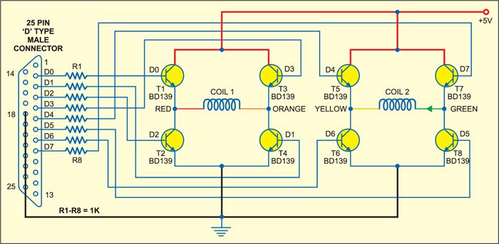
H-Bridge driver: H-Bridge is a standard, well-known circuit widely used as stepper motor driver. It is a bridge connection of four transistors (see Fig. 1). Because there are two coils in the bipolar stepper motor, two H-bridge circuits, one for each coil, have been used. One H-bridge is formed by transistors T1 through T4 and the other bridge is formed by transistors T5 through T8.

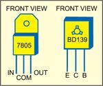
Transistors T1 through T8 are BD139 type and should be used with heat-sinks. Pin details of BD139 and regulator IC 7805 are shown in Fig. 2. The bases of all the eight transistors are connected to data pins (D0 through D7) of the 25-pin, D-type male connector through 1-kilo-ohm current limiting resistors R1 through R8.
The bases of transistors T1 and T4 are connected to parallel-port pins 2 (D0) and 3 (D1) through resistors R1 and R2, respectively, and the bases of transistors T2 and T3 are connected to parallel-port pins 4 (D2) and 5 (D3) through resistors R3 and R4, respectively. The red and orange terminals of the first coil (COIL1) are connected to the first H-bridge section as shown in Fig. 1.
The bases of transistors T5 and T8 are connected to pins 6 (D4) and 7 (D5) through resistors R5 and R6, respectively, and the bases of transistors T6 and T7 are connected to pins 8 (D6) and 9 (D7) through resistors R7 and R8, respectively. The yellow and green terminals of the second coil (COIL2) are connected to the second H-bridge section as shown in Fig. 1.
Power supply
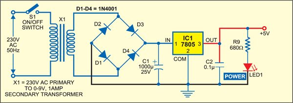
The power supply section is shown in Fig. 3. It consists of a 230V AC to 9V AC, 1A secondary transformer (X1), filter, bridge rectifiers and 5V DC regulator 7805 (IC1). The regulated 5V DC is connected to the H-bridge circuits. The circuit ground is shorted to pins 18 through 25 of the D-type parallel-port connector. When switch S1 is closed, LED1 glows to indicate the presence of power in the circuit.
Operation
Specific sequence of pulses are given to the red and orange terminals of COIL1 and yellow and green terminals of COIL2 to rotate the motor either in clockwise or anticlockwise direction as explained in the following paragraph.
Direction control
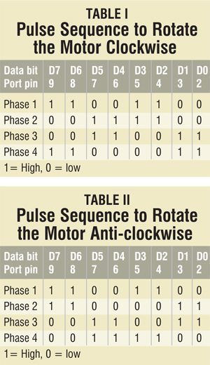
In Tables I and II, ‘0’ indicates low logic and ‘1’ indicates high logic. We know that the current flows from high to low. Changing the direction of rotation is nothing but changing the direction of current that flows through the coils.
Speed control
To vary the speed, you have to vary the pulse repetition frequency (PRF). The PRF of 20 Hz means 20 pulses will be given to the stepper motor in one second. Since the step resolution of the motor is 18o/pulse, the motor will rotate 20×180=3600 (one complete revolution) in one second. So the speed of the motor is one revolution per second (RPS) or 60 RPM. Now if you increase the PRF from 20 Hz to 40 Hz, the RPS will also double to 2 RPS (120 RPM).
Number of rotations
The step resolution of 18°/pulse means if you apply only one pulse, the motor will rotate by 18°. If you apply 10 pulses sequentially, the motor will rotate 180° (half of a revolution). So if you limit the number of pulses applied to the motor, you can stop it at any angular position (multiple of 18°) after completing the desired number of full revolutions. Thus if you apply only 25 pulses, the motor will complete one full revolution and rotate further by 90º (¼ revolution) and stop.
H-bridge
The transistors in the circuit act as switches. When high logic (3.49V) is applied to any data pin of the port, the transistor connected to it conducts and acts as a closed switch, allowing the current to pass through it. When low logic (0.09V) is applied, the transistor stops conducting and acts as an open switch, so the current cannot pass through it.
The pulse sequences to be given to switch the transistors are shown in tables. The current will flow into/out of the coils through the four terminals of the motor (red, orange, green and yellow).
Clockwise rotation
In the first phase, orange and green terminals should be high and red and yellow terminals should be low. To achieve this, out of the eight transistors, four transistors (T2, T3, T6 and T7) should conduct. For this, you have to output hex data word ‘CC’ (1100 1100) from the LPT port.
In the second phase, red and yellow terminals should be high, while orange and green terminals should be low. To achieve this, only transistors T2, T3, T5 and T8 should conduct. For this, you have to output hex data word ‘3C’ (0011 1100) from the LPT port.
In the next phase, red and green terminals should be high, while orange and yellow terminals should be low. To achieve this, transistors T1, T4, T5 and T8 should conduct. For this, hex data word will be ‘33’ (0011 0011).
In the next phase, red and yellow terminals should be low, while orange and green terminals should be high. To achieve this, transistors T1, T4, T6 and T7 should conduct. For the purpose, hex data word ‘C3’ (1100 0011) has to be output from the LPT port.
Thus the data sequence to be fed to the port for clockwise rotation of the motor is CC-3C-33-C3.
Anticlockwise rotation
To rotate the motor in anti-clockwise direction, the sequence of hex data to be output from the LPT port will be CC-C3-33-3C.
Software
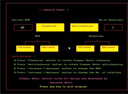
All the controlling actions are performed by the software program. The program is written in ‘C++’ language and compiled in Turbo C++ Version 3. The complete software program (STEPCNT.CPP) is given at the end of this article along with necessary comments. You require the egavga.bgi graphic file to be in the same directory as the application program to run the program. The output of the program is shown in Fig. 4.
The main functions of the software are:
- Change the direction of rotation of the stepper motor by switching the eight transistors in proper manner.
- Vary the RPM of the stepper motor accurately.
- Stop the motor at a given angular position after the desired number of complete rotations
The software is divided into three parts: graphics, stepper motor control and mouse interfacing.
Graphics
The graphics part generates complete view of the control panel. It draws buttons like clockwise, anti-clockwise and RPM increase/decrease, displays instructions, draws borderline, writes text like ‘RPM,’ ‘rotations,’ ‘number of rotations,’ etc. Graphic functions are used to make the program output screen visually appealing.
Stepper motor control
To change the direction of rotation of the motor, the program generates the desired pulse sequence, either CC-3C-33-C3 (to rotate the motor in clockwise direction) or CC-C3-33-3C (to rotate the motor in anticlockwise direction), on the parallel port with appropriate delay. The delay adjustment is done depending upon the RPM.
To vary the RPM, the program varies the PRF. First, the current RPM (S) is converted into RPS (S1) by dividing it by ‘60’ as follows:
![]()
Now for one complete revolution, you have to apply 20 pulses. So the RPS factor (S1) multiplied by ‘20’ will give you the desired PRF.
The delay (d) between the pulse sequences is given by:
![]()
When RPM is greater than ‘10,’ you can increase or decrease the RPM by a factor of ±10. For RPM less than ‘10,’ you can increase or decrease it by ±1 only. There is no limit on the maximum RPM but the minimum limit is 1 RPM.
As stated earlier, 20 sequential pulses are required for a complete revolution of the stepper motor. Since a sequence of four pulses is repeated (for clockwise or anticlockwise movement), we may say that a revolution of the stepper motor involves five identical sequences of four pulses. You can increase or decrease the number of rotations linearly by ±1. For ‘N’ below ‘1,’ you can decrease or increase ‘N’ by a factor of ‘0.5.’ The minimum limit is 0.25 (quarter revolution), but there is no maximum limit.
Mouse interfacing
This is the most interesting part of the program. It enables you to perform a task at a click of mouse. To understand how the mouse is interfaced, you have to go through the entire theory of hardware interfacing using ‘C++.’ Here, only some references have been made. For details, refer to the ‘Mouse Interfacing’ chapter of ‘Let Us C’ book by Kanitkar.
In this program, the functions that handle the mouse event are initmouse( ), resmptr(int p, int q, int r, int s), showmptr( ) and getmpos(int *t, int *u, int *v).
Functions
The initmouse( ) function loads mouse driver into the program. You’ve to pass ‘0’ value through input union REGS to the int86( ) function. This function will return some non-zero value through output union REGS to the main program. If this function returns ‘0,’ it means the mouse driver is not loaded. So the program displays the message “mouse driver is not nhbloaded” and shuts the screen off using the exit( ) function.
The resmptr(int p, int q, int r, int s) function restricts mouse movement within the boundary specified by the four variables passed to it. Pass all these boundary limits through input union REGS to the int86( ) function. So the resmptr(int p, int q, int r, int s) function will restrict mouse movement out of this boundary.
The showmptr( ) function displays mouse pointer on the program screen. For this, you just have to pass value ‘1’ through input union REGS to the int86( ) function. The showmptr( ) function will now show mouse pointer on the screen.
The getmpos(int *t, int *u, int *v) function performs two tasks: determines whether the mouse button is pressed or not, and captures the current mouse pointer position from the screen. You have to pass value ‘3’ through input union REGS to the int86( ) function. This function will return ‘x’ and ‘y’ coordinates of the mouse pointer and also return value ‘1’ if the mouse button (left) is pressed or ‘0’ if the button is not pressed.
How the program works?
The program output screen includes the control panel for speed, direction and number of rotations of the stepper motor.
The program continuously checks for mouse-click event. Whenever there is a mouse click, the getmpos( ) function instantly captures ‘x’ and ‘y’ coordinates of the mouse pointer and passes them to the main program.
The main program decides on which position the click event has occured. If the click event occured on any button (clockwise, anti-clockwise, etc), it performs the desired task. For example, if you click the ‘RPM increase’ button, the program gets the coordinates and directly switches them to ‘if’ loop, increases the RPM and also displays it on the screen.
Construction and operation
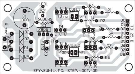
Construct the hardware on a breadboard or on a PCB. A single side PCB layout is shown in Fig. 5 and its component layout in Fig. 6. Connect the bases of the transistors to the respective data pins of the port DB25 (25-pin, D type male connector) as shown in Fig. 1. Insert DB25 into the PC’s LPT-port female connector. Connect all the coil terminals (red, orange, green and yellow) to respective points as shown in the schematic.
Apply 5V DC supply to the circuit and connect the 5V stepper motor with its terminals as shown in Fig. 1. Now run the program on a computer powered by Windows 95/98 operating system. You will see the control panel on the computer screen. Switch on the 5V supply and LED1 will glow. Move the mouse pointer to any of the buttons as desired.
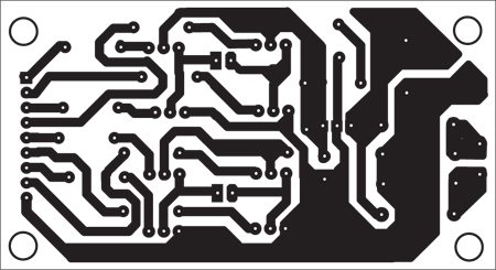
Download PCB and component layout PDFs: click here
To rotate the motor clockwise, press and hold ‘clockwise’ button with left mouse button on the control panel. Similarly, for anticlockwise rotation, press and hold ‘anticlockwise’ button. The motor will rotate in the desired direction along with the beep sound as long as the button is kept pressed. When you release the button, the beep sound as well as the motor will stop.
If the motor rotates in anticlockwise direction when you press ‘clockwise’ button, just reverse any pair of terminals of the motor coils.
Run the stepcnt.exe file on your computer. You will see the control panel for the PC based stepper motor controller on your screen. Default RPM and number of rotations are 60 RPM and 1, respectively. If you press ‘clockwise’ or ‘anticlockwise’ button, the motor will rotate until the desired rotations complete. You can increase or decrease the RPM or even the number of rotations by simply left-clicking that button once. Pressing these buttons more than once will increase/decrease the RPM/number of rotations by the same amount.
The RPM and the number of rotations are perfectly calibrated for this particular stepper motor and you will get the accurate result for the RPM. That means if you choose 1 RPM, the motor will complete one revolution in one minute exactly. For the number of rotations also, if you choose one rotation, the motor will complete only one rotation. If you choose 0.25, the motor will complete only quarter revolution (90o).
Note
The stepper motor you choose should have the same specifications as given in this project. For checking the specifications, the stepper.cpp sample program in ‘C++’ has been included in the EFY-CD. In the program, first enter RPM as ‘60’ and then the number of rotations as ‘1.’ Select clockwise or anticlockwise direction and then press ‘Enter’ key.
The program will now display the PRF (=20 Hz) and the current RPM (=60) with a melodious sound output.
If the motor doesn’t rotate, it means you have connected its four terminals wrongly. You can correct this using trial-and-error method. If the motor runs in a direction opposite to that you have selected, just reverse one pair of the coil terminals.
Because you have entered one rotation with 60 RPM, the motor will complete only one rotation in one second. If it doesn’t, your stepper motor has some different specification. To check the specifications of the stepper motor, in the sample program select RPM as ‘5’ and change the number of rotations (like 1.25, 1.5, etc) to get the step resolution. The delay factor (d) can be changed in the software. When you are satisfied with the result, switch to main program ‘stepcnt.exe’.
Download source code: click here
The article was published n October 2005 and has recently been updated.
