


We designed a Quiz Buzzer circuit that can be used for eight players/teams in quiz competitions organized by schools or colleges.
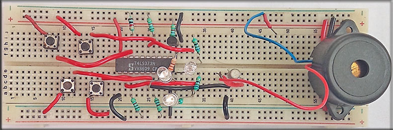
Normally, quiz circuits are designed with microcontrollers, but this simple circuit does not use any microcontroller. The heart of this circuit is a priority encoder, 74LS373. The author’s prototype built on a breadboard is shown in Fig. 1.
Components Required
| Parts List | |
| Semiconductors: | |
| IC1 | -LM7805, 5V voltage regulator |
| IC2 | -74LS373 priority encoder |
| T1, T2 | -2N2219 NPN transistors |
| BR1 | -1A bridge rectifier |
| LED1-LED9 | -5mm LEDs |
| Resistors (all 1/4-watt, ±5% carbon): | |
| R1 | -1-kilo-ohm |
| R2-R10 | -5.6-kilo-ohm |
| R11-R18 | -100-ohm |
| Capacitors: | |
| C1 | – 1000μF, 35V electrolytic |
| Miscellaneous: | |
| CON1 | – 2-pin connector |
| S1-S8 | – Push-to-on switches |
| X1 | – 230V AC primary to 9V, G39 500mA secondary transformer |
Quiz Buzzer Circuit
Fig. 2 shows the circuit diagram for the quiz competition buzzer.

It is built around a step-down transformer (X1), a bridge rectifier (BR1), a 5V voltage regulator LM7805 (IC1), eight push-to-on switches (S1 through S8), priority encoder IC 74LS373 (IC2), two NPN transistors 2N2219 (T1, T2), a piezo buzzer (PZ1), nine LEDs (LED1 through LED9), and a few other components.

EFY++ CONTENT: ACCESS TO THIS CONTENT IS FREE! BUT YOU NEED TO BE A REGISTERED USER.

Hello, Are you connecting this to an Arduino? Is it possible to access your code? I’m just a beginner. Thank you