
Adders in Digital Circuit and ALU (Arithmetic logic units) for the addition of numbers and also responsible for calculating the addresses and table indices, increment/decrement operators. The Half Adder is one type of this adder family.
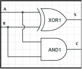
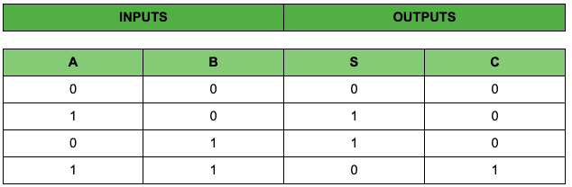
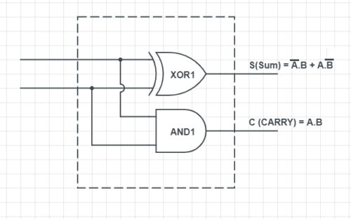
It is an arithmetic digital circuit that takes two inputs called binary digits (0,1) and adds them to give two outputs named SUM and CARRY. From the given truth table we can observe that the half adder circuit is achieved by the combination of X-OR and AND Logic gates. Sum (S) of bit gets constructed by the X-OR gate and Carry (C) by using AND gate.
The Sum (S) of a bit gets constructed by the X-OR gate and Carry (C) is obtained by using AND gate. The Boolean logic for Sum (S) is A’.B+ A.B’ and for Carry (C) is A.B.The INPUT variables for the half-adder are known as addend and addend bits.
You might ask what is the need to carry?
Let’s understand that. Binary bits consist of 0 and 1. If we add two single bits like “0+0”, ”1+0” or “0+1”, we get a result of either ”0“ or “1“. In normal addition, 1+1 is 2. But in binary addition, 1+1 is 10. Here, we have an extra output 0 which we need to carry.
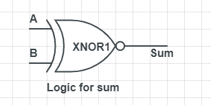
Logic diagram for the sum X-OR gate where Inputs are the two single binary digits.
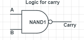
Logic diagram for carrying is achieved by And gate with two inputs of single binary digit.
Truth Table
Let us also read about Half adder
Full adder is needed when we want to add more than one binary digit quantity,
It takes three inputs and gives two outputs. The input consists of A and B and the third one is the C-IN (Carry Input). The output consists of S (sum) and C-OUT (Carry out). The full adder circuit can be made with the help of two half adder circuits.
For reading other interesting articles like this: click here