


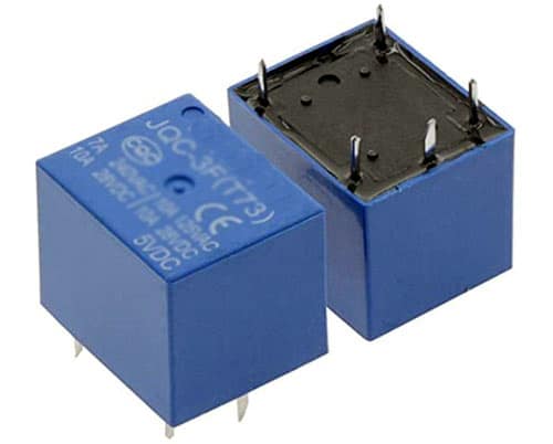
An electrical relay switch is a solid-state or electromechanical switch that uses a low-power signal to operate a high-power circuit. It can switch currents electronically using semiconductor devices or manually using an electromagnet to activate a switch.
Table of Contents
Relays come in a variety of forms, including solid state and electromechanical, which are the more common types. Though there are many different kinds of relays, all of them have the same mechanism.

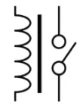
Every electromechanical relay includes an:
- Electromagnet
- Mechanically movable contact
- Switching points and
- Spring
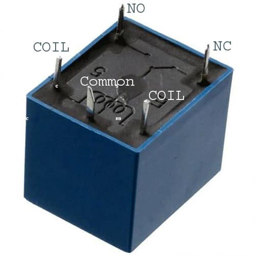
A copper coil is coiled around a metal core to create an electromagnet. As indicated, the two ends of the coil are linked to two relay pins. These two serve as pins for the DC supply.
Two additional connections, referred to as switching points, are typically required to connect a high ampere load. To connect the switching points, a second contact known as the common contact is necessary.
These contacts are designated as ordinarily open (NO), normally closed (NC), and common (COM).
A relay can be used in an alternating current or direct current circuit. In the case of AC relays, for every current zero state, the relay coil becomes demagnetized, increasing the possibility of the circuit breaking repeatedly.
To overcome this particular difficulty, AC relays are built with a specific mechanism that allows for continuous magnetization. Electronic circuit arrangement and shaded coil mechanism are examples of such mechanisms.
Also Check: Causes of Relay Failure
Relay Operating Principle
The below diagram shows functioning of Relay:
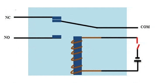
- Relays operate on the principle of electromagnetic induction.
- When an electromagnet is charged with current, it generates a magnetic field around itself.
- The image depicts the working of the relay. A switch is used to supply DC current to the load.
- In the relay, the copper coil and iron core operate as electromagnets.
- When the coil is fed with DC current, it begins to attract the contact, as shown. The process is known as relay energizing.
- When the supply is removed, it returns to its previous position. This is called de-energizing of the relay.
There are other relays with contacts that are initially closed and then opened when there is a supply, which is exactly the reverse of the relay pictured above.
Solid state relays will contain a sensor element that detects the input voltage and switches the output via opto-coupling.
Different Types of Relay Contacts
As we know, a relay acts as a switch. The term “poles and throws” is also applicable to relay. Relays are classified according to the number of contacts and circuits they switch.
Let’s take a look at poles and throws of a relay switch.
Poles and Throws: Relays can control one or more circuits. Each switch in the relay is referred to as a pole. Throws represent the number of circuits that a relay connects.
Relays are classified according to the poles and throws:
- Single Pole Single Throw
- Single Pole Double Throw
- Double Pole Single Throw
- Double Pole Double Throw
Single Pole Single Throw
A single pole single throw relay is capable of controlling one circuit and connecting to a single output. It is useful for applications that only require an ON or OFF state.
Single Pole Double Throw
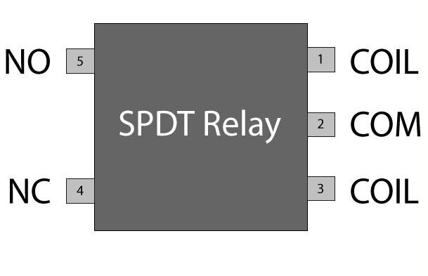
One input circuit is connected to one of the two outputs via a single pole double throw relay. This relay is also known as a “changeover relay.”
Despite having two output slots, the SPDT may have more than two throws depending on the application’s design and requirements.
Double Pole Single Throw
A double pole single throw relay has two poles and a single throw, allowing it to link two terminals of a single circuit at once. For example, this relay is used to connect both phase and neutral terminals to a load at the same time.
Double Pole Double Throw

A DPDT (double pole, double throw) relay features two poles and two throws per pole. In motor direction control, these are used to reverse phase or polarity.
When the coil is activated, all of these relays’ contact’s switch.
Types of Relays
- Electromagnetic Relay (EMR): An electromagnet is used to mechanically open and close connections.
- Solid-State Relay (SSR): Currents are switched using electrical components rather than moving parts.
- Reed Relay: Contains magnetic reed switches that are actuated by an electromagnet and allow for quick switching in modest currents.
- Thermal Relay: Operates on heat generated by the relay, which is widely used for overload protection.
- Time Delay Relay: In timing applications, the switch is turned on or off after a certain time delay.
- Latching Relay: Even when the control signal is gone, it retains its state (open or closed) until a new control signal arrives.
- Relay with Multiple Poles/Throws: For complex circuits, several switching contacts can be used, such as SPDT (Single Pole Double Throw) or DPDT.
Relay Switch Circuits
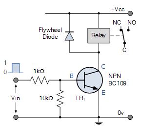
NPN Relay Switch Circuit
When the Base voltage of the transistor is zero (or negative), the transistor is cut-off and acts as an open switch. In this condition, no Collector current flows and is de-energised because being current devices, if no current flows into the Base, then no current will flow through the coil.
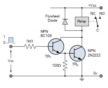
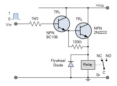
NPN Darlington Relay Switch Circuit
The two NPN transistors are connected so that the Collector current of the first transistor, TR1 becomes the Base current of the second transistor TR2. The application of a positive base current to TR1 automatically turns “ON” the switching transistor, TR2.
Emitter Follower Relay Switch Circuit
Common Collector or Emitter follower configuration is very useful for impedance matching applications because of the very high input impedance (~hundreds of thousands of Ohms) while having a relatively low output impedance to switch the coil.
Emitter Darlington Relay Switch Circuit
A very small positive Base current applied to TR1 causes a much greater Collector current to flow through TR2 due to the multiplication of the two Beta values.
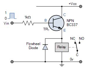
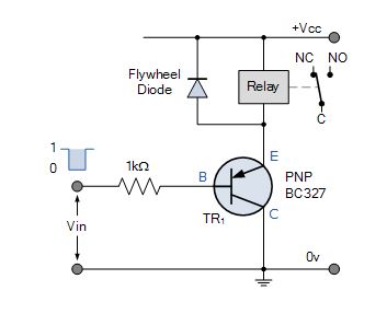
PNP Relay Switch Circuit
This circuit requires different polarities of operating voltages. Load current flows from the Emitter to the Collector when the Base is forward biased with a voltage that is more negative than that at the Emitter. For the relays load current to flow through the Emitter to the Collector, both the Base and the Collector must be negative in respect to the Emitter.
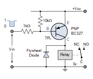
PNP Collector Relay Switch Circuit
The relay load is connected to the PNP transistors Collector. The ON-OFF switching action of the transistor and coil occurs when Vin is LOW, transistor “ON” and when Vin is HIGH, transistor “OFF”.
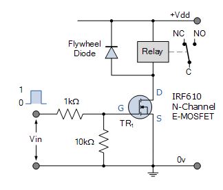
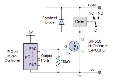
N-channel MOSFET Relay Switch Circuit
The MOSFET relay switch circuit is connected in common-source configuration. With zero voltage input, LOW condition, the value of VGS, there is insufficient Gate drive to open the channel and the transistor is “OFF”.
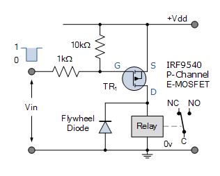
P-channel MOSFET Relay Switch Circuit
When a HIGH voltage level is applied to the Gate, the P-channel MOSFET will be turned “OFF”. The turned “OFF” E-MOSFET has a very high channel resistance and acts nearly like an open circuit. When a LOW voltage level is applied to the Gate, the P-channel MOSFET will be turned “ON”.
Logic Controlled Relay Switch Circuit
A relatively small positive voltage greater than the threshold voltage VT, on its high impedance Gate causes it to begin conducting current from its Drain terminal to its Source terminal. Unlike the bipolar junction transistor which requires a Base current to turn it “ON”, the e-MOSFET only requires a voltage on the Gate as due to its insulated Gate construction, zero current flows into the gate.
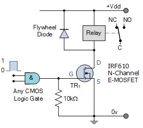
BJT’s make for good and cheap relay switching circuits, but they are current operated devices. They convert a small Base current into a larger load current to energize the coil. However, the MOSFET switch works better as an electrical switch as it takes virtually no Gate current to turn it “ON”, converting a Gate voltage into a load current. Therefore, a MOSFET can be operated as a voltage-controlled switch.
Advantages of Electrical Relays
- Electrical Isolation: Provides total isolation between the control circuit and the load to ensure safety.
- Low Power Control: Uses a low-power signal to control high-power circuits, which saves energy.
- Versatility: Can be utilized for a variety of applications, including switching, timing, and protection.
- Cost-effectiveness: Typically, inexpensive for basic switching applications.
- Reliability: Mechanical relays are reliable and can withstand high voltage and current demands.
Disadvantages of Electrical Relays
- Slower Response: Electromechanical relays may be slower than solid-state relays.
- Wear and tear: Mechanical parts degrade with time, requiring maintenance or failure.
- Arc Formation: High voltage or current can generate electrical arcs at contacts, shortening the relay’s life.
- Bulky Size: Electromechanical relays can be bulkier than solid-state choices.
- Noise: Relays with moving parts may emit audible clicking sounds when in use.
Applications of Electrical Relays
- Automotive: Used to operate lights, horns, and starting motors.
- Industrial Control Systems: Industrial control systems are widely utilized for motor control, overload protection, and automation.
- Home Appliances: Home appliances include heating systems, air conditioners, and washing machines.
- Telecommunication Systems: In telecommunications systems, relays help route signals or control circuits in networking equipment.
- Power Systems: In the instance of a malfunction, power lines or transformers are turned on or off to protect the electrical grid.
Also Check: How To Use Relays for Real-World Applications?
People Also Ask
What is the main function of a relay?
A relay is used to operate a high-power circuit using a low-power signal, allowing electrical isolation across the control and load circuits.
What is the difference between an electromagnetic and solid-state relay?
Electromagnetic relays utilize mechanical parts to open and close contacts, whereas solid-state relays use semiconductor chips to switch circuits electronically, with no moving parts.
Why is isolation important in relays?
Isolation keeps the high-power circuit from interfering with or causing damage to the low-power control circuit, assuring both safety and signal integrity.
How do you choose the right relay for an application?
Consider voltage, current ratings, switching speed, number of poles/throws, and the relay’s operating environment (such as temperature and humidity).
Can a relay switch AC and DC?
Yes, relays can switch both AC and DC loads; however, the relay’s requirements must match the kind of current being used.