Fluorescent bulbs
Fluorescent (CFL) bulbs are highly efficient light sources, with efficacies of up to 100 lm/W. Development of the fluorescent bulb dates back to the 1800s, but Edmund Germer is given the credit for making this technology feasible in 1926. General Electric later purchased Germer’s patent for fluorescent technology and brought fluorescent bulbs into widespread use by 1938.
The fluorescent bulbs work by conducting current through a tube that is filled with mercury vapour. The vapour ionises to produce ultraviolet light. The tube has a phosphorous coating which shifts the light output to the visible spectrum.

How to drive a fluorescent bulb?
Fluorescent bulbs cannot operate directly from a power supply because of their negative impedance properties. As the current flow in the tube increases, the internal resistance decreases. This results in a run-away effect. A ballast device is required to limit the current. The ballast could be as simple as a current-limiting resistor, but it is very inefficient. Inductor ballasts have traditionally been used to control fluorescent bulb current. The inductor solution also allows an auto transformer circuit to be implemented, which steps up the line voltage to the bulb’s required level.
Starting the fluorescent bulb
To start a fluorescent bulb, the input voltage must be raised to a ‘strike’ voltage that causes current to flow in the bulb. The strike voltage produces the initial arc in the bulb. After the strike, the resistance of the bulb rapidly decreases.
Fluorescent bulbs are available in pre-heat, rapid-start and instant-start varieties. These types of bulbs differ in the way the filaments are heated prior to striking the arc. The pre-heat type bulbs use an external starting switch to momentarily connect the filaments in series. Rapid-start bulbs use only the starting voltage to heat the filaments. Instant-start bulbs do not require filament heating and can be recognised by a single terminal at either end of the bulb. A voltage that is high enough to strike the arc without heating is applied to the bulb.

Rapid-start bulbs have the best characteristics, especially for electronic ballast applications. Though these bulbs are less efficient than other types because the filaments are continuously heated, less stress placed on the filaments results in longer bulb life.
Electronic ballasts
Fig. 2 shows the circuit that is commonly used to implement an electronic ballast, which offers better efficiency than inductor ballasts.
A resonant circuit using an inductor and capacitor is placed in series with the lamp. The L-C circuit values are chosen such as to provide resonance at the switching frequency, when the lamp is operating. Typically, electronic ballasts use switching frequencies in the range of 20-50 kHz. A second capacitor placed across the lamp effectively connects the two filaments in series at frequencies higher than the resonant frequency. Typically, the starting frequency is 100 kHz.
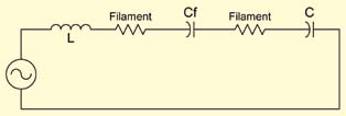
During the filament heating cycle (high-frequency), Cf conducts and the circuit looks as shown in Fig. 3. After certain time duration of filament heating, the frequency is reduced to start the lamp. Cf becomes an open circuit at the lower frequency. Before the lamp starts, the resistance of the bulb is high and the voltage rapidly rises to the strike voltage, due to the resonance of the inductor-capacitor circuit. The strike voltage is typically 600V AC or higher.
After the arc is struck, the resistance of the bulb falls and the equivalent circuit looks as shown in Fig. 4. The voltage across the bulb also drops dramatically and is usually less than 100V AC.
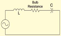
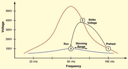
Fig. 5 shows the graphical representation of the operating stages of an electronic fluorescent ballast.
Generating a precise variable frequency from a digital PwM module
A typical pulse-width-modulation (PWM) peripheral on an MCU can easily be used to generate variable-frequency oscillation (VFO) required for ballast applications. The PWM module is well suited for generating variable pulse widths at a fixed frequency, but may not have the frequency precision required for the ballast application. This is especially true if dimming is required. The dimming of a fluorescent bulb can be accomplished by increasing the frequency away from the resonant frequency of the drive circuit. Fortunately, there is an easy way to solve the problem using software.