


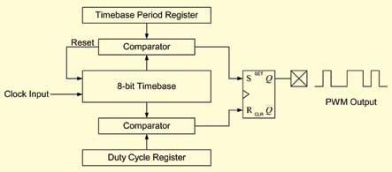
Fig. 6 shows a typical digital PWM peripheral found on an MCU. There is a digital timebase and associated period register that sets the PWM signal period. A third register is used to set the duty cycle of the PWM.
To make the things easy, let us assume that the timebase is clocked from a 10MHz source. Further, assume that the centre frequency required for the ballast circuit is 50 kHz. A value of 200 would be loaded into the period register to get a 50kHz output signal. For good dimming adjustments, you need to be able to vary the frequency in 0.1 per cent (50Hz) steps. If the period register changes to ‘199,’ an output frequency of 50,251 Hz results. So we need a way to increase the frequency resolution by a factor of ‘5.’

The frequency resolution can be increased by forcing the PWM module to switch between two adjacent periods over time. At the end of each PWM period, a value is added to an accumulator register. The value added to the register represents the fractional portion of the required period. If the register overflows as a result of the addition, the higher of the period values is written to the PWM module in order to produce a lower frequency. If the register does not overflow, the lower period value is used.
Assuming that the PWM module has an 8-bit period register and the accumulator register is also 8-bit, you effectively have a 16-bit register for setting the PWM period. Stated another way, you have added eight fractional bits to the frequency-adjustment resolution.
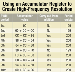
To generate a frequency of 50,050 Hz, the required period value is 199.8. The PWM period register is set to a value of ‘200’ 80 per cent of the time, and a value of ‘199’ 20 per cent of the time. The value added to the 8-bit accumulator register is 0.8×256=204=0xCC.

The table shows how the algorithm works over several PWM periods. The period register of the PWM module is changed between 199 and 200 over time, so the average period of 199.8 is produced.
With the 8-bit accumulator used in this example, the effective frequency can be adjusted in 10Hz steps around the centre frequency of 50,000 Hz. This resolution provides excellent dimming performance in electronic ballast applications.
Power LEDs
LEDs have been widely used in indicator applications for years. The indicator (or winky-blinky) style LEDs are low-current, low-power devices that are not very suitable for lighting applications. However, recent advances in semiconductor manufacturing, silicon structures and phosphor coatings have made high-power LEDs possible.
Present-day power LEDs have a high efficacy that approaches or exceeds that of other efficient light sources. LEDs also offer other benefits like long lifetime and resistance to shock and vibration. These benefits make the LEDs useful for traffic signs, automotive lighting, military applications or any place where safety, reliability or the cost of maintenance could be an issue.
Power LEDs are manufactured with a silicon-carbide or sapphire substrate. The sapphire substrate offers a lower manufacturing cost, but higher thermal resistance. Silicon carbide can be more attractive because of its lower thermal resistance, which is extremely important for power LED applications.
The substrate is then doped with AlInGaP to make the LED red, orange or yellow in colour. Or, the substrate can be doped with AlInGaN to make green, blue or white LED. The colour produced by the LED is a function of the doping (the lens over the LED) and the phosphorous coating that is applied beneath the lens.
White light
The ability to make a white light source with an LED is very important for lighting applications. There are two common methods for making a white LED. The first is to use a blue LED with a phosphor coating that creates a white light. The other method uses an LED that emits light in the ultra-violet range. A mix of red, green and blue phosphors is then used to turn the UV light into visible white light.
There are some pros and cons of each of these methods. The blue-LED+phosphor method provides a very efficient light source. On the downside, it is difficult to control the exact colour of the light output because of variations in the blue LED. The UV LED+RGB phosphor construction provides a more predictable colour because the properties of the phosphor determine the colour of the light output. A disadvantage of this technique is that the red phosphor tends to degrade faster than other phosphors, causing a shift towards cool white.
Another way to produce white light with LEDs is to use three emitters for red, green and blue. If the LEDs are driven in the right proportions, you get white light. Similar to the UV+RGB phosphor type of LED, the colour of the three-LED solution tends to drift as each LED ages differently. In critical applications, active sensing and control can be used to correct the three-LED white light source, over time.
Thermal issues with LEDs
As stated before, heat dissipation and thermal resistance are big issues with power LEDs. A power LED does not radiate heat. This means, unlike incandescent bulbs, you will not feel the heat when you get near the power LED. Instead, the heat generated by an LED must be mechanically conducted away from the junction.
Power LEDs could not be viable without the same assembly techniques as used to make power semiconductors. Winky-blinky LEDs have a junction that is encapsulated by an insulating, epoxy lens. This leaves only the leads to conduct heat away from the junction. In contrast, power LEDs, like other semiconductor devices, are manufactured on a chip. This chip is then fixed to a heat slug that penetrates through the package, and the connections are made to external terminals by bonding wires. The slug is then encapsulated with a silicone gel and covered with a hard plastic lens that is coated with phosphorus. This encapsulation method avoids stress on the bonding wires. The epoxy lens will not be practical, because of thermal expansion.
Heat is the biggest enemy of power LEDs. However, the lifetime of LEDs can exceed 50,000 hours, in comparison to 8000 hours of fluorescent bulbs and 2000 hours of incandescent bulbs. To achieve such a long lifetime, the junction temperature of the LED must be kept low. The actual temperature limit is a subject of debate among major LED manufacturers, but, in general, the junction temperature must be kept at 80°C or less to achieve a long lifetime.

