Imagine you have a powerful AC motor that needs to run at different speeds for different tasks. You could simply vary the voltage, right? But what if you also need to tweak the frequency to get smoother control over the speed and torque? That’s where a cycloconverter comes into play—an unsung hero in the world of industrial electronics.
In this article, we’ll unpack everything you need to know about cycloconverters: how they work, their types, where they’re used, and why they matter. Let’s break it down, step by step.
Table of Contents
What is a Cycloconverter?
A cycloconverter is an electronic device that converts AC power at one frequency to AC power at another frequency—without first converting it to DC. That’s right—unlike typical power converters that use rectifiers and inverters in tandem, cycloconverters skip the DC stage altogether. They’re often used to reduce the frequency of the power supply to drive large motors, especially in heavy-duty applications.
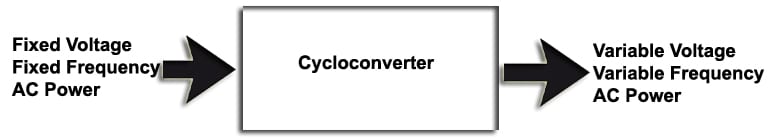
So, think of it this way: a cycloconverter takes your 50 Hz AC input and gives you a much slower output, say 16.67 Hz, which is ideal for running large motors at lower speeds but with high torque.
Why Are Cycloconverters Important?
In industries like steel manufacturing, mining, and ship propulsion, motors often need to operate under variable speed and load conditions. Traditional motor control methods either fall short or waste a lot of energy. Cycloconverters help by:
- Delivering variable frequency output
- Enabling precise motor speed control
- Supporting high torque at low speeds
- Eliminating the bulky DC link stage
They’re efficient, reliable, and built for high power levels—often above 1 MW.
How Does a Cycloconverter Work?
At the core, a cycloconverter works by controlling the firing angles of power electronic switches—usually thyristors or SCRs (Silicon Controlled Rectifiers). These switches chop segments of the input AC waveform and stitch together a new waveform at the desired (usually lower) frequency.
There are two groups of switches involved:
- One for the positive half of the output waveform
- Another for the negative half
These operate alternately to construct a waveform that closely follows a sine wave at the new frequency.
Note: Cycloconverters can only reduce the frequency—they’re step-down by nature. Step-up cycloconverters exist, but they’re complex and rarely used.
Types of Cycloconverters
Cycloconverters come in a few different flavors, and each has its unique use case.
1. Based on Frequency Conversion
- Step-Down Cycloconverter: Output frequency is lower than input. Most commonly used.
- Step-Up Cycloconverter: Output frequency is higher than input. Rare and complex.
2. Based on Phase
- Single-phase to Single-phase
- Three-phase to Single-phase
- Three-phase to Three-phase (used for industrial motors)
3. Based on Operating Mode
- Blocking Mode: Only one group of thyristors is active at a time. Safer and simpler.
- Circulating Current Mode: Both positive and negative groups conduct simultaneously. Better waveform, but requires additional reactors.
Control Methods
Controlling a cycloconverter is a bit like conducting an orchestra—you need precise timing and coordination. Here are a few popular strategies:
- Phase Angle Control: The simplest and most widely used method.
- Pulse Width Modulation (PWM): Helps shape a cleaner output waveform.
- Vector Control or Direct Torque Control: Used in advanced motor drives for dynamic performance.
As the control method improves, so does the output waveform—getting closer to a pure sine wave, which motors love.
Key Characteristics
Before you decide to use a cycloconverter, here are some of its defining traits:
- Output Frequency Range: Usually limited to less than one-third of the input frequency.
- Harmonic Distortion: High, but manageable with filters.
- Bidirectional Power Flow: Allows for regenerative braking in motors.
- Four-Quadrant Operation: Can handle forward and reverse torque and rotation.
Applications of Cycloconverters
Cycloconverters shine brightest in high-power, low-speed applications. Some real-world examples include:
- Steel Mills: To control the speed of rolling mill motors.
- Marine Propulsion: Efficient speed control for large marine engines.
- Mine Hoists and Crushers: Where torque control is critical.
- Aircraft Ground Power Units: Convert standard AC to 400 Hz.
- Railway Systems: Especially for older electric trains that use 16.67 Hz.
They’re not meant for small appliances or consumer electronics—they belong in the heavy-duty world.
Advantages
- High efficiency (up to 98%)
- Excellent for low-speed, high-torque motors
- Compact design with no DC link
- Works well in four-quadrant operations
Limitations
- Complex control circuitry
- Generates harmonics
- Costlier than VFDs (Variable Frequency Drives) in low to medium power applications
- Limited to reducing frequency
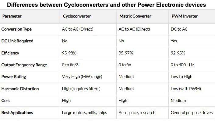
Cycloconverter vs Modern Alternatives
While cycloconverters are powerful, newer technologies like Matrix Converters and PWM-based VFDs are gaining ground due to better waveform quality, smaller size, and digital control options.
Still, for high-power, low-speed needs, cycloconverters are hard to beat. They’re rugged, proven, and still in use in legacy systems around the world.
Also Check: GaN-Based Single-Phase Cycloconverter Reference Design
Final Thoughts
Cycloconverters may not be the flashiest tech in the electronics world, but they’re incredibly important in industries where power, precision, and control matter most. Whether it’s hoisting a mine elevator or turning the massive screw propeller of a ship, cycloconverters get the job done.
So, next time you come across a large AC motor moving slowly with immense torque, there’s a good chance a cycloconverter is working behind the scenes.
Frequently Asked Questions
Q1: Can a cycloconverter increase frequency?
Technically, yes, but it’s rare and impractical. Most cycloconverters are used to reduce frequency.
Q2: What is the efficiency of a cycloconverter?
Efficiency ranges from 95% to 98%, depending on load conditions and control method.
Q3: What are the alternatives to cycloconverters?
PWM-based inverters and matrix converters are modern alternatives, especially for medium power levels.
Q4: What is the typical output frequency range?
Usually, it’s below one-third or one-half of the input frequency for best performance.