Before going deep into the working of a thyristor, let’s understand why it is needed when we already have a tiny component named transistor that can help us in switching and amplification.
While a transistor can perform switching, they are not good at handling large amounts of current. Another problem with the transistor is that they gets turned OFF when we remove the switching current.

Table of Contents
When we want to trigger and the switching current is removed, we need another device because the transistor fails here. To solve both of the above problems, a thyristor is required. Besides handling a large amount of current, it can also run continuously even if the switching current is removed.
What is a Thyristor?
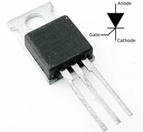
A thyristor is a four-layer solid-state semiconductor device that contains 3 PN junctions in series having 3 terminals called anode, cathode, and gate. Like a diode, a thyristor is a unidirectional device as well but unlike diode, it can be used as an open circuit switch.
Working Principle of a Thyristor
In a thyristor, the silicon wafer is doped with four alternate P and N types, which looks like two transistors connected back-to-back (as seen in the pic below).

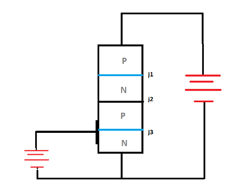

Here, the P (cathode) and the N (anode) are joined in series, thus, we get three terminal pins: anode, gate, and cathode.
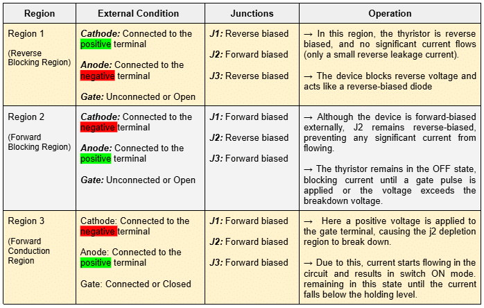
When we forward bias the anode and cathode i.e. anode and cathode connected to the positive and negative terminals of a battery, the first PN junction and last PN junction (j1 and j3) become forward biased due to break of the depletion layer. The junction j2 remains as reverse-biased as no current is provided to the gate.
When we supply current to the gate, then the J2 junction layer starts breaking and the current starts flowing in the circuit. When a sufficient positive signal current or pulse is applied to the gate terminal, it triggers the thyristor into a conducting state.
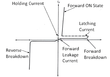
A thyristor can only be fully on or off, which means it cannot lie in between On and Off states similar to transistors. This makes a thyristor unsuitable as an analog amplifier, but useful as a switching device.
Thyristor’s Three Working Modes:
Now, we will discuss the V-I curve of the thyristor. There are three regions of thyristor’s operation based on the behaviour of junctions J1, J2, and J3.
Types of Thyristors and Uses
There are generally 3 different kinds of thyristor:
1. Silicon Controlled Rectifier
SCRs are four-layer, three-junction semiconductor devices that can conduct current in one direction. SCRs are used to control huge currents and are generally used as high-frequency switches in an electrical circuit.
Application: Power control, lighting control, heating control, motor control, etc.
2. Gate Turn OFF Thyristor – GTO
GTOs are a type of thyristor that can be turned off by the application of a negative gate current. This makes them a fully controllable switch.
Application: Inverters, AC drives, induction heaters, etc.
3. Insulated Gate Controlled Bipolar Transistor – IGBT
IGBT is a type of power semiconductor device that combines the benefits of MOSFETs and Bipolar transistors.
Applications: They are used in SMPS (Switched-mode power supply), motor control, induction heating, etc.
We use thyristor as a switching circuit where we have to control motors and operate ON/OFF lamps.
Note: Thyristor devices are mainly used where high voltage and current are involved and are often used to control alternating currents (AC)
Thyristor Comparison with Other Semiconductor Devices
| Feature | Thyristor | Diode | Transistor |
| Definition | Semiconductor device used to control power. It also acts as a switch | Semiconductor device that acts as a one way switch | Semiconductor device used to amplify and regulate current or voltage flow |
| Structure | Four-layer(P-N-P-N) | Two-layer(P-N) or (N-P) | Three-layers(P-N-P) or (N-P-N) |
| Terminals | 3 (Cathode, Anode, Gate) | Two (Cathode, Anode) | Three (Collector, Emitter, Base) |
| Control | Gate control for triggering ON | No control terminal | Base current controls the collector-emitter current |
| Switching Behavior | Latches ON once triggered until current drops | Turns OFF immediately in reverse bias | Can switch ON and OFF with varying base current |
| Applications | Power control, speed control, light control, etc. | Rectifiers, voltage regulators, LEDs, oscillators, etc. | Logic circuits, amplifiers, switches, etc. |
Advantages of Thyristor
- High voltage current handling
- Efficient power control
- Fast switching
- Lower conduction losses
Disadvantages of Thyristor
- Compared to transistors, thyristors have limited switching speed
- Complex control requirement
- Reverse blocking limitations
- Sensitivity towards noise and voltage spikes
Applications of Thyristor
- AC & DC motor speed control
- Phase control in power supplies
- ON/OFF lamps
- Inverters
- Timer circuits
Common Challenges in Usage
| Challenges | Solutions |
| The thyristor may not turn ON due to insufficient gate current or incorrect triggering methods. | Ensure the gate signal is within the current and voltage specifications. Verify the triggering circuit for proper design |
| The thyristor may turn ON unintentionally | This may be due to the noise, voltage spikes, or interference. Use filters, proper grounding techniques, and shielding mechanisms |
| High junction temperature | Ensure adequate cooling mechanisms, and monitor thermal conditions regularly |
| Problem of reverse breakdown | Verify that the applied reverse voltage does not exceed the thyristor’s rating Ensure the thyristor is connected to the right polarity |
People Also Ask
What is the purpose of the gate terminal in a thyristor?
The gate terminal is used to trigger the thyristor into conduction. When a small pulse of current is applied to the gate, then the device is turned ON, allowing current to flow between the anode and cathode.
What is the difference between a thyristor and an SCR?
An SCR (Silicon Controlled Rectifier) is a thyristor type. All SCRs are thyristors, but not all thyristors are SCRs. SCRs are the most commonly used type of thyristor for switching and rectifying.
What is “latching” in a thyristor?
Latching is a characteristic where, once the gate pulse triggers ON the thyristor, it continues to conduct current even after removing the gate signal. It will remain ON until the current falls below the holding level.
What is “holding current” in a thyristor?
The minimum current required to keep the thyristor in the ON state. If the current flowing through the device drops below this level, the thyristor will turn OFF.
What is forward breakover voltage in a thyristor?
Forward breakover voltage is the voltage at which a thyristor switches ON without any gate signal. If the voltage across the anode and cathode exceeds this value, the thyristor will turn ON even without triggering from the gate.