


Under normal conditions, transistor T1 is cut off and collector output is high around 6V. When motion is sensed, output pin (OUT) of the sensor becomes high, making transistor T1 to conduct for a few seconds, and voltage at its collector goes low momentarily. This low signal triggers IC2. Output pin 3 of IC2 goes high for around ten minutes, energising relay RL1 through transistor T2, turning on the load for ten minutes.
In brief, when someone comes in front of the PIR module, its output triggers IC2 to turn on the load. Thereafter it is disabled automatically.

Download PCB and Component Layout PDFs: click here

Construction and testing
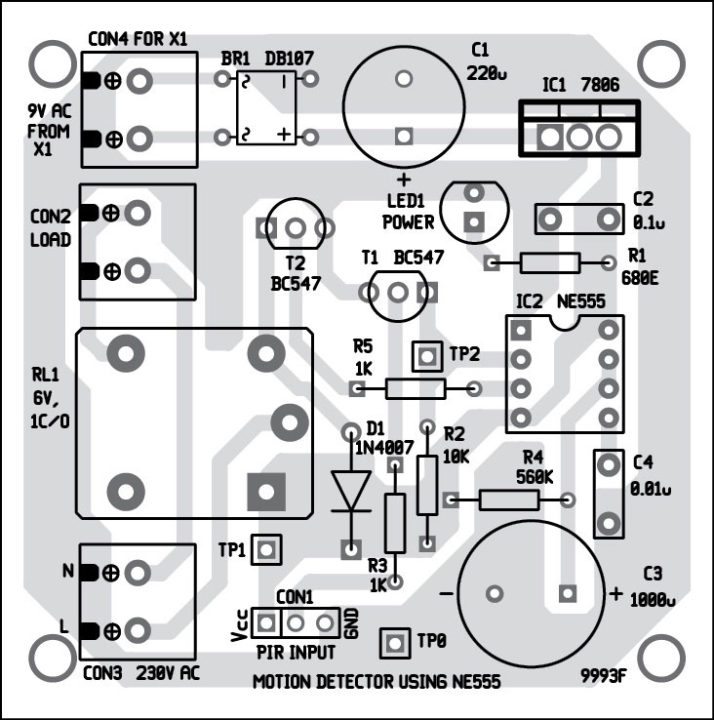
An actual-size, single-side PCB for the motion detector using NE555 timer is shown in Fig. 2 and its component layout in Fig. 3. Enclose the PCB in a box and install it at a suitable location. Connect the PIR module across CON1.
Connect transformer X1 to 230V AC mains. Verify various test point voltages as given in the table to ensure proper working before using the circuit.
Kumar Abhisekh is a third-year student of B.Tech (electronics and communication) at SETGOI, Institute of Engineering & Industrial Technology, West Bengal
cant we operate it on 5v dc power supply like mobile charger, it would have been easy.
yes gowhar.. you can do it, but this project include 6v dc relay, so it can’t be operate,
Better to use capacitor power supply for such Application.
can we use pir sensor without arduno
Yes, you can use PIR sensor without Arduino or microcontroller
sensitivity control?
Kindly elaborate your query.
Is the circuit working??
I tried it by replacing the load by a buzzer but it keeps ringing. Please help thank you ? ?
kindly check the register. you may also use variable register
How to reset timer when second motion detected???
ITS Not working, IC and voltage regulator are over heated.When initially power on relay is activated and not sensing the circuit
is this is a microcontroller basaed project
Sir please help
It’s not working .When initially power ON the relay is activated and not sensing .I remove the sensor but relay not OFF
The circuit not reset
The relay should not get energised without PIR sensor input. First check proper connections in the circuit including correct polarities and orientations of various active components. If connections are ok, make sure that voltage at pin 2 of NE555 is high when sensor is not connected and low when sensor is connected and motion is detected.
Note that when power is switched on, the relay will energise for around ten minutes. If relay is not de-engerise even after ten minutes, first check whether transistor BC547 is faulty or connected in wrong position. If it is ok, next check IC2.
The relay should not get energised without PIR sensor input. First check proper connections in the circuit including correct polarities and orientations of various active components. If connections are ok, make sure that voltage at pin 2 of NE555 is high when sensor is not connected and low when sensor is connected.
instead of transformer ,,, how to supply 9v to this device
sir
i want to make a muscal buzer with the use of bt66 transister and 27mm 3-pin piezo,
i have been try many time but i’m not 100% succes.
so please help me
What is the range of PIR mean from how much area can be covered.
how can i connect the transformer to the circuit? please help. im currently making this project
try solder
Why you did’t use a transistor to switch relay instead of using 555 ic. As there are no time events, this circuit can be made by only switching the transistor when pir sensor pin give output.
if you didn’t use the 555 ic there will be no timer to stop the load after 10 minutes