


 A moving message display is ideal to get your message (advertisements, greetings, etc) across in an eye-catching way. You can make an LCD show a brief moving message by interfacing it to a microcontroller. Here’s an AVR-based moving message display that uses a 16×2 LCD display incorporating HD44780. The 16×2 LCD can display 16 characters per line and there are two such lines.
Moving message display circuit
Fig. 1 shows the circuit for AVR ATmega16-based moving message display on an LCD. It consists of an ATmega16 microcontroller, a 16×2 LCD, an SPI6 connector and a power supply section.
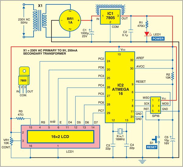
To derive the power supply for the circuit, 230V AC mains is stepped down by a 9V, 250mA secondary transformer, rectified by bridge rectifier module BR1A and filtered by capacitor C1. The voltage is regulated by a 7805 regulator. LED1 glows to indicate the presence of power in the circuit. The regulated 5V DC powers the entire circuit including SPI6 connector.

Port-C pins PC4 through PC7 of the microcontroller (IC2) are connected to data lines D4 through D7 of the LCD. The LCD control lines—read/write (R/W), register-select (RS) and enable (E)—are connected to PD6, PC2 and PC3 of IC2, respectively.
Why AVR microcontroller?
AVR is faster and more powerful than 8051 microcontroller, yet reasonably cheaper and in-circuit programmable. Most AVR development software are free as these are Open Source. Moreover, discussions and tutorials on the AVR family of processors are available on the Internet.

ATmega16 is a high-performance, low-power 8-bit AVR microcontroller. It has 16 kB of in-system self-programmable flash, 1 kB of internal SRAM, 512 bytes of EEPROM, 32×8 general-purpose working registers and JTAG Interface (which supports programming of flash, EEPROM, fuse and lock bits).
On-chip peripheral features
1. Two 8-bit timers/counters with separate pre-scaler and compare modes
2. One 16-bit timer/counter with separate pre-scaler, comparator and capture modes
3. Four pulse-width-modulation channels
4. 8-channel, 10-bit analogue-to-digital converter
5. Byte-oriented two-wire serial interface
6. Programmable serial USART
7. Master/slave serial peripheral interface
8. Programmable watchdog timer with separate on-chip oscillator
LCD display module
The project uses a Hitachi HD44780-controlled LCD module. The HD44780 controller requires three control lines and four or eight input/output (I/O) lines for the data bus. The user may choose to operate the LCD with a 4-bit or 8-bit data bus. If a 4-bit data bus is used, the LCD will require a total of seven data lines—three lines for sending control signals to the LCD and four lines for the data bus. If an 8-bit data bus is used, the LCD will require a total of eleven data lines—three control lines and eight lines for the data bus.
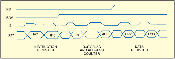
The enable control line is used to tell the LCD that the microconroller is sending the data to it. To send data to the LCD, first make sure that the enable line is low (0). When other control lines are completely ready, make enable pin high and wait for the LCD to be ready. This time is mentioned in the datasheet and varies from LCD to LCD. To stop sending the data, bring the enable control low (0) again. Fig. 2 shows the timing diagram of LCD control lines for 4-bit data during write operation.
When the register-select line is low (0), the data is treated as a command or special instruction (such as clear screen and position cursor). When register-select is high (1), the text data being sent is displayed on the screen. For example, to display letter ‘L’ on the screen, register-select is set to high.
When the read/write control line is low, the information on the data bus is written to the LCD. When read/write is high, the program effectively queries (or reads) the LCD. This control command can be implemented using ‘C’ programming language.
For 4-bit interface data, only four bus lines (D4 through D7) are used for data transfer. Bus lines D0 through D3 are disabled. The data transfer between HD44780 and the microcontroller completes after the 4-bit data is transferred twice.
Controlling a standard numeric LCD is not that difficult. To display text on the LCD, correct library files for the LCD are needed. Many LCD libraries are available on the Internet, which are used in various applications. You may get confused which library is suitable for your application.
Libraries for LCDs found in AVRLIB library occupy unnecessary program memory space. To solve the problem, you can write your own library for LCD control.
Software program
This project demonstrates sending the text to the LCD controller and scrolling it across the LCD. For the project, AVR Studio 4 and WINAVR software need to be installed in your PC. Three program codes are used here—movm.c, lcd2.c and lcd2.h. The movm.c contains the text message to be scrolled on the LCD. lcd2.c and lcd2.h are the library files. The programming technique given here may not be the best as it uses a simple logic, but it works pretty fine.
The LCD library for 4-line or 4-bit mode operation is used here. Each pin connected to the LCD can be defined separately in the lcd2.h code. The LCD and AVR port configurations in the C code along with comments are given below:
[stextbox id=”grey”]#define LCD_RS_PORT LCD_PORT
LCD port for RS line
#define LCD_RS_PIN 2
PORTC bit 2 for RS line
#define LCD_RW_PORT PORTD
Port for RW line
#define LCD_RW_PIN 6
PORTD bit 6 for RW line
#define LCD_E_PORT LCD_PORT
LCD port for enable line
#define LCD_E_PIN 3
PORTC bit 3 for enable line[/stextbox]
Enable control line
The E control line is used to tell the LCD that the instruction for sending the data on the data bus is ready to be executed. E must always be manipulated when communicating with the LCD. That is, before interacting with the LCD, E line is always made low. The following instructions toggle enable pin to initiate write operation:
[stextbox id=”grey”]/* toggle enable pin to initiate
write * /
static void toggle_e(void)
{
lcd_e_high();
lcd_e_delay();
lcd_e_low();
}[/stextbox]
The complete subroutine of this code can be found in lcd2.c.
The E line must be left high for the time required by the LCD to get ready for receiving the data; it’s normally about 250 nanoseconds (check the datasheet for exact duration).
Busy status of the LCD
It takes some time for each instruction to be executed by the LCD. The delay varies depending on the frequency of the crystal attached to the oscillator input of the HD44780 as well as the instruction being executed.
While it is possible to write the code that waits for a specific amount of time to allow the LCD to execute instructions, this method of waiting is not very flexible. If the crystal frequency is changed, the software needs to be modified. Additionally, if the LCD itself is changed, the program might not work even if the new LCD is HD44780-compatible. The code needs to be modified accordingly.
The delay or waiting instruction can be implemented easily in C language.
In C programing, the delay is called using the delay( ) function. For instance, delay(16000) command gives a delay of 16 milliseconds.
Initialising the LCD
Before using the LCD, it must be initialised and configured. This is accomplished by sending a number of initialisation instructions to the LCD.
In WINAVR GCC programming given here, the first instruction defines the crystal frequency used in the circuit. This is followed by a standard header file for AVR device-specific I/O definitions and header file for incorporating program space string utilities. The initialisation steps in movm.c file are as follows:
[stextbox id=”grey”]#define F_CPU 16000000
#include
#include
#include
#include “lcd2.h”
#define RATE 250[/stextbox]
Clearing the display
When the LCD is first initialised, the screen should automatically be cleared by the HD44780 controller. This helps to clear the screen of any unwanted text. Clearing the screen also ensures that the text being displayed on the LCD is the one intended for display. An LCD command exists in ‘Assembly’ to accomplish this function of clearing the screen. Not surprisingly, the AVR GCC function is flexible and easy to implement.
Refer the code given below:
[stextbox id=”grey”]lcd_init(LCD_DISP_ON);
lcd_clrscr();[/stextbox]
Here the first line is for LCD initialisation (turn on the LCD) with cursor ‘off.’ The second line clears the display routine to clear the LCD screen.
Writing text to the LCD
To write text to the LCD, the desired text is put in the memory using the char string[ ] function as follows:
[stextbox id=”grey”]char string[] PROGMEM=”WECOME TO
ELECTRONICS FOR YOU – NEW DELHI”;[/stextbox]
The program makes this text scroll on the first line and then the second line of the LCD. The speed of scrolling the text on the LCD screen is defined by “# define RATE 250” in the beginning of the movm.c code. To start with, first the LCD screen is cleared and then the location of the first character to appear on the screen is defined. Getting the text from the program memory and then scrolling it on the LCD screen continuously is achieved using the following code:
[stextbox id=”grey”]
while(j<=(len-1))
{
lcd_clrscr();
lcd_gotoxy(0,0);
for(k=0,i=j;(k<16) && ( pgm_
read_byte(&string[i])!=’\0’
);k++,i++)
{
lcd_putc(pgm_read_
byte(&string[i]));
}
WaitMs(RATE);
j++;
}
[/stextbox]
Compiling and programming
Compiling the movm.c to generate the movm.hex code is simple. Open AVR Studio4 from the desktop and select new project from ‘Project’ menu option. Select AVR GCC option and enter the project name. Next, select ‘AVR Simulator’ and click ‘Ok’ button.
First, copy the three codes (movm.c, lcd2.c and lcd2.h) to your computer. Import the movm.c and lcd2.c files into ‘Source Files’ option on the left side of the screen. Next, import the lcd2.h file into ‘Header Files’ option. Select the device as ATmega16 and tick the box against ‘Create Hex’ option in the project configuration window. Now click ‘Rebuild All’ option in ‘Build’ menu. If the code is compiled without error, the movm.hex code is generated automatically under ‘Default’ folder of the project folder.
To burn the hex code into ATmega16, any standard programmer supporting ATmega16 device can be used. There are four different AVR programming modes:
1. In-system programming (ISP)
2. High-voltage programming
3. Joint test action group (JTAG) programming
4. Program and debug interface programming
Here two options for burning the hex code in standard ISP mode are explained. Some AVR tools that support ISP programming include STK600, STK500, AVRISP mkII, JTAGICE mkII and AVR Dragon. There are also many other AVR programming tools available in the market.
PonyProg2000 software
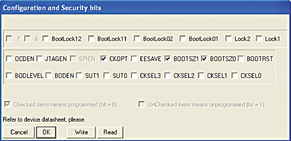
This software along with programmer circuit is available from www.lancos.com/prog.html website. After installing PonyProg2000, select the device family as AVR Micro and device type as ATmega16. Now in ‘Setup’ menu, select ‘SI Prog’ I/O option for serial programmer and COM port from ‘Interface Setup’ option. In ‘Security and Configuration Bits’ option, configure the bits as shown in Fig. 3. Next, open the device file (hex code) and click ‘Write All’ option to burn the chip.
Frontline TopView software
This software along with programmer board is available from www.frontline-electronics.com website. After installing the software, select COM port from ‘Settings’ menu. In ‘Device’ menu, select the device as ATmega16. Burn the hex code into the chip by clicking ‘Program’ option. Note that the microcontroller uses a 16MHz externally generated clock. Program the fuse bits in the software by selecting upper and lower bytes as follows:
[stextbox id=”grey”]Fuse low byte = EF
Fuse high byte = C9[/stextbox]
If the fuse bits are not configured properly, the text will scroll slowly or text scrolling may not function properly even if the scrolling rate in the code is changed. The SPI6 connector allows you to program the AVR using SPI adaptor in ISP mode.
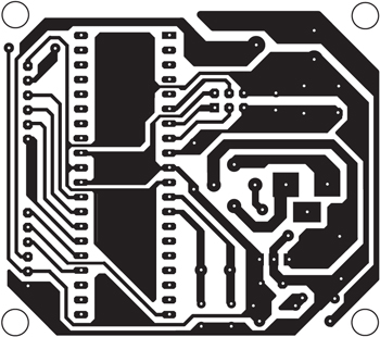
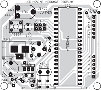
Download PCB and component layout PDFs: click here
Construction and testing
A single side PCB for the moving message display using AVR is shown in Fig. 4 and its component layout in Fig. 5. Before mounting the AVR onto the PCB, ensure proper power supply to the circuit. Program the AVR as mentioned above, insert it into the PCB and power-‘on’ the circuit. The text will scroll from right to left in the first line and then in the second line of the LCD, repeatedly. If there is any problem in the display, press reset switch S1 momentarily. If there is no message display at all, vary the contrast-control preset (VR1) until the text is visible on the LCD.
Download source code: click here
The article was originally published in Jukly 2012, and has been updated recently.
Feel interested? Check out other electronics projects.

Here in this project, 3 codes are given namely movm.c,lcd2.c and lcd2.h . I am confused among these 3 codes which code to be burn in the IC. Please give me the suitable suggestion.
How to calculate the value of c1 & c2. Pls tell the for this
Plz provide me the source code of this project