


This project builds a Video Surveillance robot that can be controlled via wireless remote control and can be used for video surveillance also.
Video surveillance is the process of monitoring a situation, an area or a person. This generally occurs in a military scenario where surveillance of borderlines and enemy territory is essential to a country’s safety. Human surveillance is achieved by deploying personnel near sensitive areas in order to constantly monitor for changes. But humans do have their limitations, and deployment in inaccessible places is not always possible.
There are also added risks of losing personnel in the event of getting caught by the enemy. With advances in technology over the years, it is possible to remotely monitor areas of importance by using robots in place of humans.

We have developed a robot which can be used for video surveillance & monitoring which can be controlled through a GUI interface. The control mechanism is provided with a video transmission facility. The video transmission is practically achieved through high-speed image transmission. Initially, the robot will be equipped with a camera which will capture the scenes and transfer the images to the server on which the user will be controlling and watching the live feed.
Block Diagram
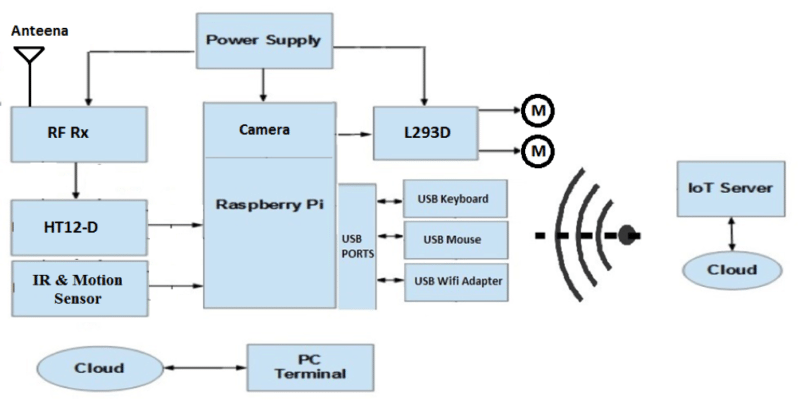
The brain of the circuit is Raspberry pi. It is single board credit card size computer based on A 900MHz quad-core ARM Cortex-A7 CPU with 1GB RAM.

It is also equipped with two IR obstacle sensors which allow it to see the obstacles that you can’t, because well, you’re not there. It will detect an object and if the object detected, it will change its direction. As stated before, the robot has quite a few sensors on board. It also has a camera which can be used for video surveillance of human beings.
We have also used a motion sensor to detect human movement. If a human is detected, the system will enable a camera module. It also has an L293 motor driver to allow sufficient current to power the motors via the Raspberry pi GPIO. We have established IoT server which enables to controlled robot from a remote place.
Necessary packages required
• We have flash Raspbian OS in microSD card. Raspbian is a free operating system based on Debian optimized for the Raspberry Pi hardware. An operating system is the set of basic programs and utilities that make your Raspberry Pi run.
• We have to control robot from webpage so we need to install necessary package related to server.
For installation of the apache server do following steps
• sudo apt-get install apache2 –y
• To allow your Apache server to process PHP files, you’ll need to install PHP5 and the PHP5 module for Apache. Type the following command to install these:
• Sudo apt-get install php5 libapache2-mod-php5 -y
After installing apache2 server on raspberry pi we can test it by running following link from browser.
http://localhost/ OR http:// “ IP Address of Raspberry Pi”
Browse to the default web page either on the Pi or from another computer on the network and you should see the following:
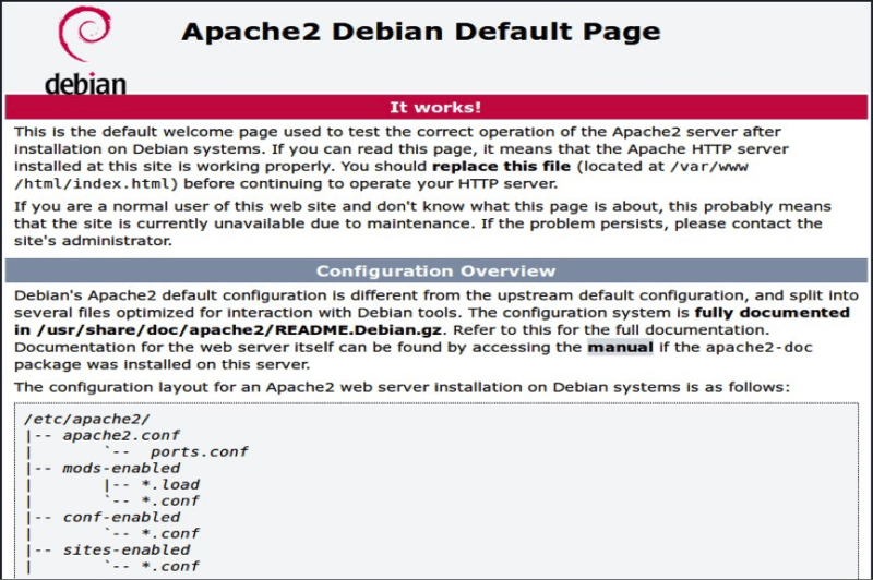
This means you have Apache working!
This default web page is just a HTML file on the file system. It is located at /var/www/html/index.html.
Now you can remove that index.html file by executing following command.
rm index.html
Copy all the files provided in attached zip file to /var/www/html folder and then run following link on browser from raspberry pi or other device which is connected on same network.
http://localhost/ OR http:// “ IP Address of Raspberry Pi”
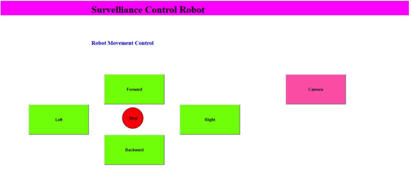
Hence you should able to see following robot controlling webpage.
Component list
| Device Name | Quantity |
| Raspberry Pi 2 | 1 |
| Power Bank (5V) | 1 |
| Sd card (8GB) | 1 |
| RF-Module (Tx-Rx- Pair) | 1 |
| HT12E | 1 |
| HT12D | 1 |
| Battery (12V-1.2A) | 1 |
| Robot Chassis | 1 |
| Wheel | 4 |
| Motor (12V-200RPM) | 2 |
| L293D | 1 |
| Switches On-off | 4 |
| Cell Battery (1.5V) | 2 |
| USB Wi-Fi Adapter (Edimax) | 1 |
| IR Sensor (Pair) | 2 |
| Motion Sensor | 1 |
| Raspberry pi Camera | 1 |
| Connectors | Required as per implementation |
Circuit description
This video surveillance robot is controlling by two possible ways
• Robot movement control by wireless Remote (within 100m distance).
• Robot movement control by web browser from anywhere.
The circuit is divided into transmitter and receiver sections. The transmitter section consists of an RF Transmitter, HT12E encoder IC and four push buttons.
Transmitter
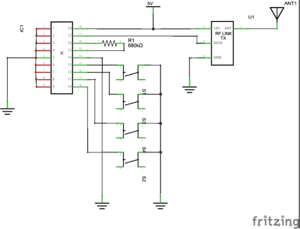
The circuit shown in fig operates using 1.5V(3 cell).HT12E is an encoder IC that converts the 4-bit parallel data from the 4 data pins into serial data in order to transmit over RF link using the transmitter. A 680 KΩ resistor is connected between the oscillator terminals of encoder IC. This is to enable the oscillator.
There are four switches is connected with HT12-E IC which will be used to control the movement of the robot.
We have connected all address to ground on both transmitter and receiver side.
Pin 17 of HT12E is directly connected to the data pin of RF-Tx, so RF-Tx will radiate signal which has information of input status. The receiver will collect the signal and decode it.
Main Circuit
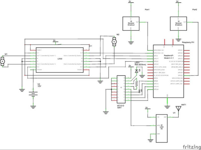
The circuit shown in fig operate using power bank. A Raspberry Pi required 5V supply which is provided through power bank. The receiver section consists of RF Receiver, HT12D Decoder IC. An extra LED is connected to VT (Valid Transmission) pin of the decoder IC. This is used to indicate a successful transmission of data. Similarly, a 33 KΩ resistor is connected to the oscillator pins of decoder IC.
As well as we are proving output of HT12D (data pin) to raspberry pi so Raspberry Pi will decide the direction of the robot. We have attached two IR sensors with the robot which can detect the object if any object detected then the robot will stop and turn right/turn left according to distance/position of an object.
We have used an L293D motor driving circuit to control the motor movement because the output of the raspberry pies nowhere strong enough to drive dc motor directly. This is a very useful chip. It can control two motors independently. We can also control the speed of the motor using PWM output. But in raspberry pi, we have only one PWM channel so we can control only one motor speed.
The L293D has two +V pins (8 and 16). The pin ‘+Vmotor (8) provides the power for the motors, and +V (16) for the chip’s logic. We have connected pin 16 to the 5V pin of the Pi and pin 8 to a battery pack.
| Enable | A | B | Result |
| HIGH | High | Low | Forward |
| HIGH | Low | High | Backward |
| HIGH | High | High | Stop |
| HIGH | Low | Low | Stop |
You can see the truth table to understand more about direction controlling of robot.
Robot controlled from Internet
In order to control the robot from Internet, we have written a python script which will read web link continuously, and do necessary movement according to the input received from the web link. We are using 6 Tab in our GUI (Graphical User Interface) forward, backward, right, left, stop and camera.
When the user gives a particular input from the webpage, it will be stored in a text file on the server, at the robot end python script is running continuously which will read that text file and make movement decision according to user input. Raspberry pi will give output to L293D which will be used for controlling direction of motor according to received input from Raspberry pi.
Hence when the user clicks on the forward button, the robot will move in the forward direction and website will redirect to the index.html page so that user can give another command. Let’s say if the user hits the right button, in this case, only one motor (back-left motor) will be enabled and the robot will move in the right direction.
In order to turn on camera user will have to click on Turn On button provided in GUI. Once camera gets turned on, user able to see the front view from robot by pressing the camera button. The user can see the front view of the camera from anywhere just user need to have connected to the internet.
We have implemented a python script which turned on camera automatically when the object is detected by IR sensor.
Application & Advantages
1) This can be used as a spy robot.
2) This robot has military application
Steps to run the project
We have to follow below steps to run the project.
• Provide supply from power bank to raspberry pi.
• When it gets booted up, we get GUI window once get GUI open terminal and execute following python script in order to control the robot from the wireless remote.
sudo python remote1.pyOpen web browser and type http://localhost/
• Once we get GUI for robot controlling click on forward.
• That’s it robot should move in forward direction. Same for other commands.
• In order to see front view of camera, user has to turn on the camera by pressing Turn On button from GUI after that user needs to press camera button.
• In order to control robot from webpage / Internet execute following python script.
sudo python rasbpi.py
Application
- At the time of war where it can be used to collect information from the enemy terrain and monitor that information at a far secure area, and safely devise a plan for the counter attack.
- Tracking locations of terrorist organizations and then plan an attack at a suitable time.
- Making video surveillance of any disaster affected area where human beings can’t go.
Feel interested? Check out these Raspberry Pi projects.

Where is the sample code?
What is the cost of project
Is it possible to stream video and control motor at the same time over INTERNET?
How to got this project
Can use a raspberry pi 3 b+ model
Soft copy of this project needed
Hi Sai, this article was published online only.Please save this webpage as PDF from your browser.
How to write the program
Can I have the code of this project? I’m very interest in this and I want to have the knowledge on this.