


Equalisation charge. It refers to equalising the capacity of the individual cells in a multicell battery. This is an important issue for improving the battery life, but requires a special controller mode to create it in a system charged by PV panels. (It involves increasing the voltage to 2.5-2.6V/cell for a short time period (0.5-1 hour) at regular intervals, say, once a week.) It can be termed as forced overcharge interval after the main charge sequence.
Generally, the voltage ranges for six-cell (12V) lead-acid batteries are:
1. Open-circuit voltage after full charge: 12.6-12.8V
2. Open-circuit voltage after full discharge: 11.8-12.0V
3. Loaded at full discharge: 10.5V
4. Float charging: 13.8V for gelled and 13.4V for wet cells
5. Typical (daily) charging: 14.2-14.5V
6. Equalisation charging (for wet lead-acid): 15-16V
Note. Above voltages are at 25°C, and need to be adjusted for temperature changes.

Charge controller design
Fixing the set points (Fig. 2). The battery voltage levels at which a charge controller performs control or switching functions are called the controller set points. Four basic control set points are defined for most charge controllers that have battery overcharge and over-discharge protection features. High-voltage array disconnect (HVD) and high-voltage array reconnect (HVR) refer to the voltage set points at which the PV array is connected and disconnected from the battery. For our example, charger HVD=14.3V and HVR=13.3V. These two set points are also referred to as voltage regulation (VR) and low voltage reconnect (LVR), respectively.
Low-voltage load-disconnect (LVD) and load-reconnect voltage (LRV) refer to the voltage set points at which the load is disconnected/reconnected from/to the battery to prevent over-discharge.
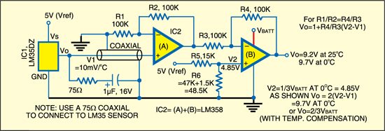
Temperature compensation. The battery capacity (Ah) is defined for cell temperature of 27°C (80°F). If the battery temperature is higher than the design condition, it will slightly increase its Ah capacity. But, this will also increase the water loss and decrease the number of cycles in the battery life. The battery life is halved if the temperature rises to 35°C (95°F) from 25°C (77°F), and at 45°C (113°F), it drops to one-quarter.
A widely accepted value of temperature compensation for lead-acid batteries is -5 mV/°C/cell. For a 12V battery, this amounts to -30 mV/°C. It is important to note that the temperature compensation (TC) coefficient is negative, meaning that temperature increase requires a reduction in the charge regulation voltage (HVD) and vice versa.
Technology choice. PWM technology is well suited for solar battery chargers. When the battery voltage reaches the regulation set point (HVD in Fig. 2), the PWM algorithm slowly reduces the charging current to avoid heating and gassing of the battery, but the charging continues to return the maximum amount of energy to the battery in the shortest time. The result is a higher charging efficiency, rapid recharging and a healthy battery at full capacity. Hence our obvious choice is the use of PWM method. It is an effective means for constant-voltage battery charging. With PWM regulation, the current from the solar array tapers off in accordance with the battery’s condition and recharging needs.

very useful article for both student and electronics professional.