


 In environments like factories, power plants and transformers in electricity substations, controlling temperature to a safe value is important. Supervisory and control systems are used to monitor the temperature and other physical parameters on a centralised machine whereby one can monitor and control the remote devices. The AVR microcontroller-based system described here does the same job of acquiring the analogue data and sending it to a remote terminal for monitoring.

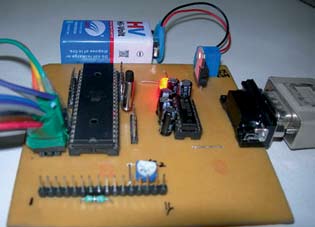
Fig.1 shows the block diagram of the eight-channel data acquisition and logging system using AVR microcontroller and Fig.2 shows the author’s prototype. The key features of this system are:
1. The software is user-friendly and written in VB 6.0.

2. Data is acquired through serial port of the PC and displayed on the screen of the PC monitor.
3. Precise analogue signal conversion using AVR analogue-to-digital converter with 10 bitre solution
4. All data acquired by the system is logged into a database for future reference with date and time of sampling.
5. The internal analogue-to-digital conversion (ADC) channels of the AVR are used to acquire real-time data in the form of analogue signal. The data is sent to the PC via UART channel.
Circuit description
Fig.3 shows the circuit of the eight-channel data acquisition and logging system using AVR. At the heart of the circuit is ATMega32 AVR microcontroller from Atmel.
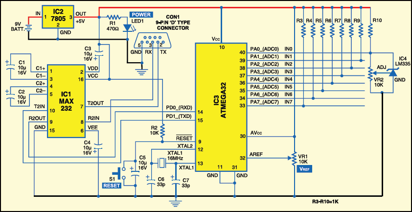
The ATMega32 microcontroller has 32 kB of flash program memory, 2 kB of SRAM, internal analogue-to-digital converter (ADC) with 10-bit resolution, internal EEPROM and full-duplex UART channel. This data logger uses ADC channels of the AVR to acquire real-time data in the form of analogue signal and sends this data to the PC via UART channel.
Vcc (pin 10) and AVcc (pin 30) of the AVR are connected to +5V for operation. By default, this AVR works with the internal RC oscillator at 1MHz. Here, fuse bits of the AVR are set to operate an external oscillator. We have used an external stable crystal oscillator to run at a frequency of 16 MHz.
The AVR has internal power-on reset facility. Resistor R2 (10-kilo-ohm), capacitor C5 (10μF) and switch S1 make up the external reset circuitry. Switch S1 allows you to reset the system at run time.
Analogue reference voltage pin VREF (pin 32) is connected to the variable terminal of the 10-kilo-ohm preset. Using this preset, you can adjust the ADC reference voltage.
We have used all the eight channels of the 10-bit ADC for acquiring the analogue voltage proportional to the environmental temperature of temperature sensors.
The in-built UART channel of ATMega32 is used to send the current data to the host PC. UART works on 9600 bauds per second. The length of RS-232 serial cable is tested for operation up to 10 metres but it should work upto 15 metres.
Data acquisition and logging
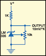
Temperature sensor. Temperature sensor LM335 from National Semiconductors has been used in this project. Its pin details are shown in Fig.4.

LM335 has a breakdown voltage directly proportional to absolute temperature at 10 mV/°K with less than 1-ohm dynamic impedance. The device operates over a current range of 400 μA to 5 mA with virtually no change in performance. LM335 can be used in any kind of temperature sensing application over the temperature range of –55°C to 150°C. Low impedance and linear output make it easier to interface with the readout and control circuitry. It is not internally calibrated for degree Celsius (°C), so you need some external circuitry in the form of a 10-kilo-ohm preset and a 1-kilo-ohm pull-up resistor as shown in Fig.5.
Calibration. Calibration is done carefully to map voltage values exactly into temperature in degree Celsius. Calibration procedure is simple. Voltage values are measured for different temperatures and a constant multiplying factor is obtained. This constant is multiplied with the current ADC value every time.
When calibrated at 25°C, typically, LM335 has an error of less than 1° over a range of 100°C. Most of all, it has a linear output. The voltage across the output terminal of LM335 is 2.982V at 25°C.
