


This microcontroller works with TTL digital logic, while the RS-232 standard specifies different voltage levels of the digital logic. So you need a signal-level converter for communication between the microcontroller and the PC over RS-232 port.
Signal-level conversion. MAX232 is used as the signal-level converter. For voltage-level conversion, four electrolytic capacitors (10μF, 16V) are used with MAX232.
There are eight input lines (IN0 through IN7) through which analogue inputs are fed into the circuit. The analogue input is converted into digital level by the AVR and transmitted to the PC through the 9-pin, D-type serial comport connector. Here, we have used only three pins of the connector (Rx, Tx and Gnd) for communication with the PC.

PC GUI software
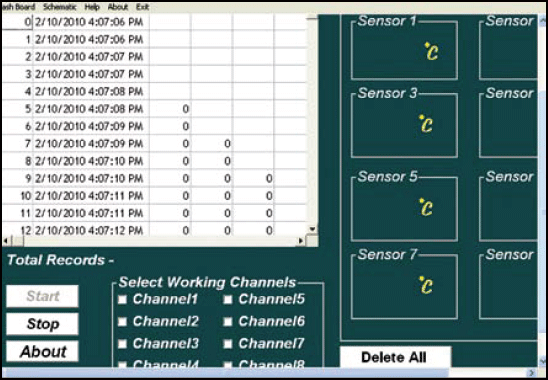
The graphic user interface (GUI) displays on the dashboard the stored data with date and time of logging. This can be useful to analyse the trend of change in temperature. The software dashboard has eight blocks for displaying data of eight different analogue channels.
The GUI software is written in Visual Basic and has MSComm ActiveX controls for communication with the serial port of the PC. It is programmed to scan real time incoming data from the external hardware. The entire working logic is asynchronous; it doesn’t matter which channel has what data. The software can capture the data from a particular channel and put it into an appropriate location in the database. A special protocol is used to synchronise the software with the hardware in order to make the program identify the data and channel number currently active on the serial port. The microcontroller first sends the channel number followed by the current captured data on the channel.
The software is calibrated such that it shows the temperature directly in degree Celsius by multiplying a calibration constant with the incoming analogue voltage.
The software is configured to work with fixed values such as ‘com1’ for the serial port and ‘9600’ for the baud rate by default. But you can easily configure it to work with different serial ports (like com2, com3 or com4) and baud rates.
The software can save data of the different input channels into a ‘daq. mdb’ database with time and date of each channel input data. Start/stop buttons are provided to start or stop the logging activity any time by the user. The GUI program output is shown in Fig.6.
Construction
A single-side, solder-side PCB layout of the circuit for eight-channel data acquisition and logging is shown in Fig.7(View as PDF) and its component layout in Fig.8(View as PDF). A 9V PP3 battery is used to power the circuit. 9V is converted into 5V using a 7805 regulator. The glowing of LED1 indicates the presence of 5V supply in the circuit. The circuit acquires analogue data from the eight channels through IN0 through IN7 inputs. The analogue temperature data at IN0 channel is acquired from LM335 temperature sensor (IC4). Temperature calibration for IC4 is done using a 10- kilo-ohm preset (VR2). The remaining inputs can be fed from external temperature sources.
Download PCB and component layout PDFs (Fig. 7. 8): click here
Assemble the temperature sensor along with preset separately on a small general-purpose PCB for each channel. Extend two wires from each of the general-purpose PCBs to the respective input points (IN1 through IN7) in the main PCB. Two-pin SIL male and female pair connector may be used for connecting the PCB to the general-purpose PCB for each channel input. As shown in Fig.5, a 10-kilo-ohm preset is used for calibration of each temperature sensor.
Calibrate each temperature sensor (LM335) before connecting the circuit to the PC. After calibration is done, install the sensors at appropriate locations or on the device whose temperature is to be monitored. Now, run the datalogger 8chnl.exe GUI software and click ‘start’ button to start the data acquisition and logging process. If data display on the dashboard is not proper, press reset switch S1 momentarily, or switch off the power supply and then switch it on. Using preset VR1, adjust ADC reference voltage such that it is exactly 5V across pin 32 of IC3.
Microcontroller firmware
The main.c source code for ATMega32 (given at the end of this article) is written in ‘C.’ It is compiled using avr-gcc cross-compiler to generate hex code. Avrdude is used to burn hex code into the ATMega32 microcontroller.
WinAVR is a free software development tool for AVR series microcontrollers hosted on the Windows platform. It has avr-gcc, avr-libc, avr-binutils and avr-dude within one package. Linux users have to install these components separately. For details of AVR programming hardware and software, visit www.electroons.com
EFY note. Click here to download the source code and other relevant files of this article.
