


In this era of digital revolution, we are surrounded by smart devices that are capable of making decisions on their own without much human intervention. Our home can also be made smart by implementing a real-time home automation system that monitors parameters like power consumption and human presence. Home automation may include centralised control of electrical devices including lightings, appliances and security.
Presented here is a touch-control based home automation system that can control up to six electrical devices. It also has a separate keyboard interface module for troubleshooting and system settings.
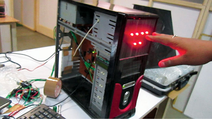
This system consists of closely-networked Atmel’s ATmega8, which is an AVR based microcontroller with 512 bytes EEPROM on a 28-pin DIP package, 1024 bytes internal SRAM and 8kB internal flash memory. The complete system is assembled in a small, portable central processing unit (CPU) chassis for an aesthetic look and uninterrupted 24×7 usage. Author’s prototype is shown in Fig. 1.

Circuit and working
The circuit has four sections: main module, relay module, touch-control module and keyboard interface module. The system is housed on the CPU chassis of a desktop computer and is powered by 400W ATX power supply for error-free operation and proper power delivery to the system.
Advanced Technology eXtended (ATX) is a motherboard form factor specification developed by Intel in 1995 to maintain the integrity and sustainability of the system.

Home automation system: main module
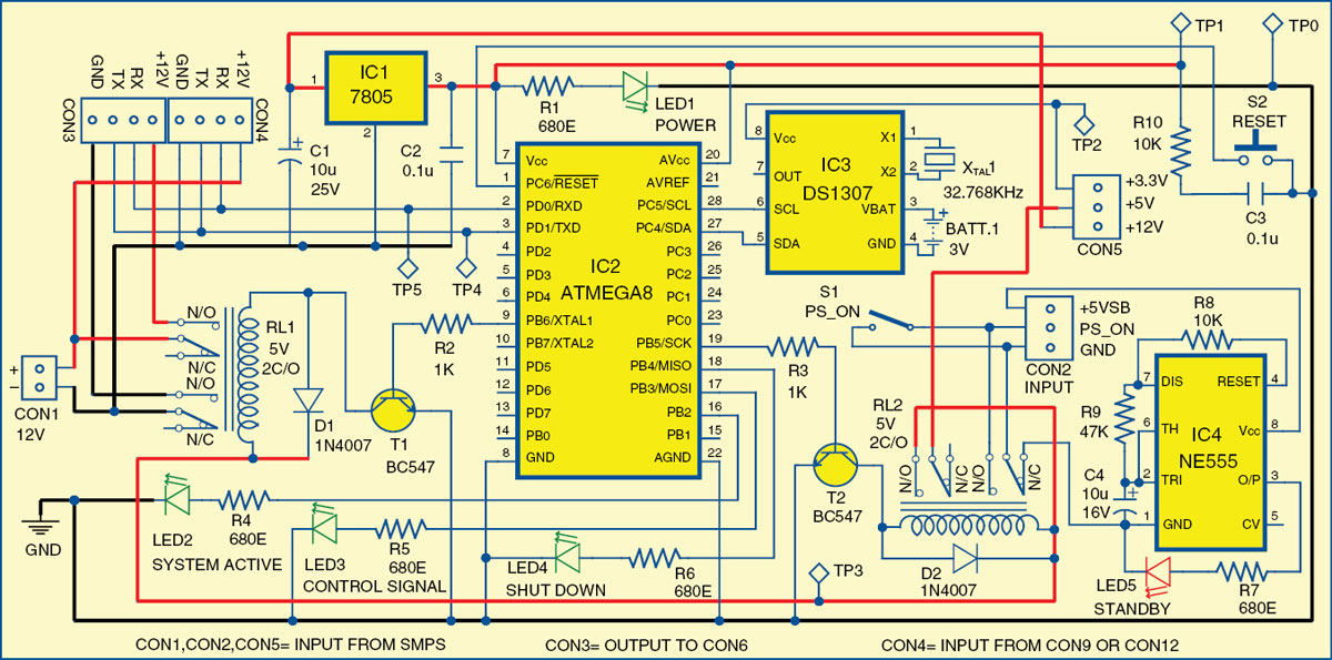
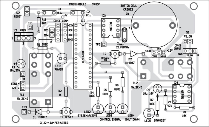
The circuit of the main module is shown in Fig. 2. It has ATmega8 microcontroller, DS1307 RTC chip and NE555 as the main components. The main module controls the load through switching relay RL1.
The system has a standby mode indicator. During standby mode, LED5 glows and power consumption is about 10mW. The ground pin of NE555 timer (IC4) is connected to GND pin of CON2 through relay RL2. LED1 is a power-on indicator and LED2 is a system-active indicator. When RL1 is energised, LED2 glows, indicating that 12V is available from CON1 to CON3 and the complete system is active.
LED3 is a device-control signal indicator that glows momentarily whenever you switch on or switch off a device. LED4 is a shut-down indicator. It glows when a shut-down command is received from the user till the system shuts down completely.
Relay interface module
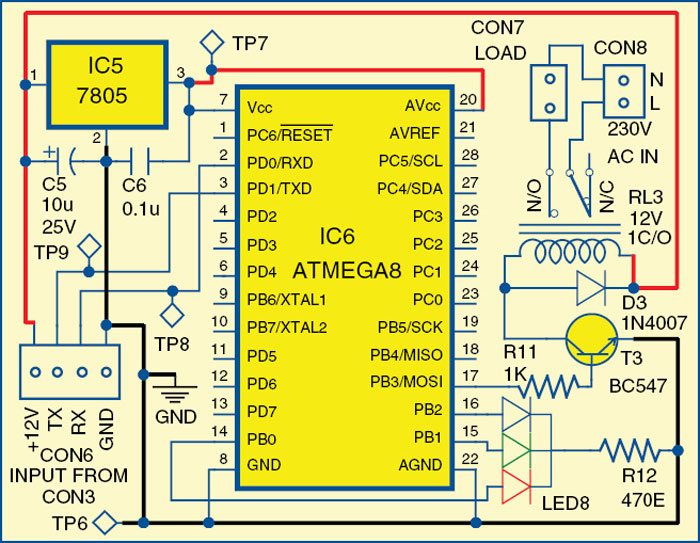
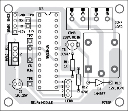
The module’s circuit is shown in Fig. 3. This module actually controls the load. For a relay to operate, a suitable pull-in and holding current should be passed through its coil. Generally, relay coils are designed to operate at a particular voltage. We have used 12V DC supply to switch relay RL3. This module receives power and data through the main module’s connector CON3 to its connector CON6. The relay module is used to connect devices. The status of the load/device is indicated by RGB LED (LED8). When power is switched on but load is off, RGB LED is red. When load is switched on, RGB LED is green.
You can replicate the same relay module circuit and extend a parallel connection at CON3 to control another load. Six or more loads can be connected in this manner.
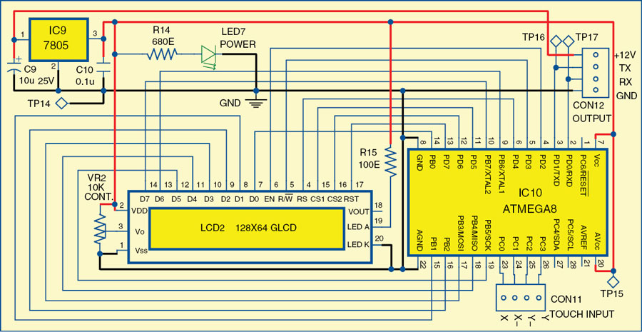
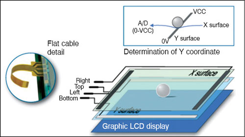
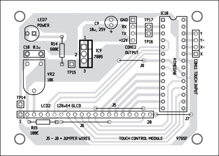
Touch-control module. This module provides various control options for controlling devices/appliances manually. The method of interfacing a touch-control module is shown in Fig. 4. The circuit has a 4-wire resistive touchscreen (not shown in Fig. 4), ATmega8 (IC10), 128×64 graphic LCD (JHD12864E), 7805 regulator (IC9) and a few other components. The touch-control panel menu includes lock/unlock, name of the device like porch light, lamp, on/off buttons, etc for controlling connected devices and also has a shutdown feature for the system. It includes a lock screen feature that switches off the LCD backlight when not in use, in order to save power.
A resistive touch panel consists of two transparent rigid foils, forming a sandwich structure that has resistive layers on its inner sides. The touch panel is easily available in mobile phone repair shops. Resistances of these layers usually do not exceed 1-kilo-ohm. Opposite sides of the foils have contacts available for use through a flat cable. This cable is connected to CON11 in the circuit.
The process of determining coordinates of the point at which the touch panel is pressed can be broken up into two steps. First is the determination of X coordinate and second is Y coordinate of the point (Fig. 5).
In order to determine X coordinate, it is necessary to connect the left contact on X surface to ground and the right contact to +5V power supply (Vcc). This enables a voltage divider to be obtained by pressing the touch panel using a stylus (or finger). If the pressing point is closer to the left contact of X surface, the voltage will be closer to 0V and the controller will determine the exact position of the point depending on the voltage obtained.
Similarly, in order to determine Y coordinate, it is necessary to connect the bottom contact on Y surface to ground and the upper contact to +5V power supply.
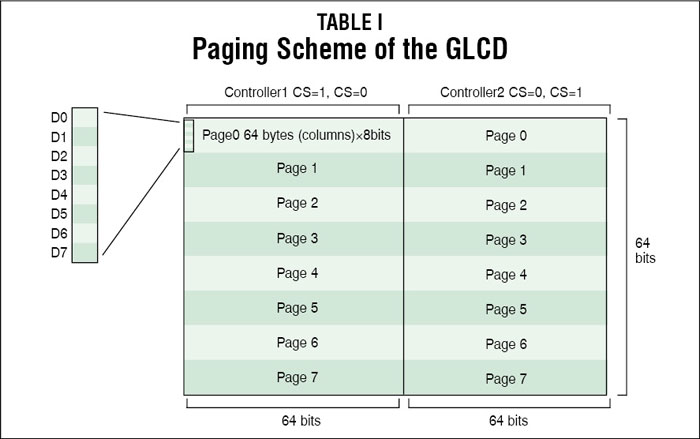
The 128×64 LCD is divided into two equal halves, with each half being controlled by a separate KS0108 controller. Such LCDs (using KS0108 controllers) involve a paging scheme, that is, the whole LCD is divided equally into pages. Paging scheme of the graphical LCD can be understood from Table I.
Keyboard interface module
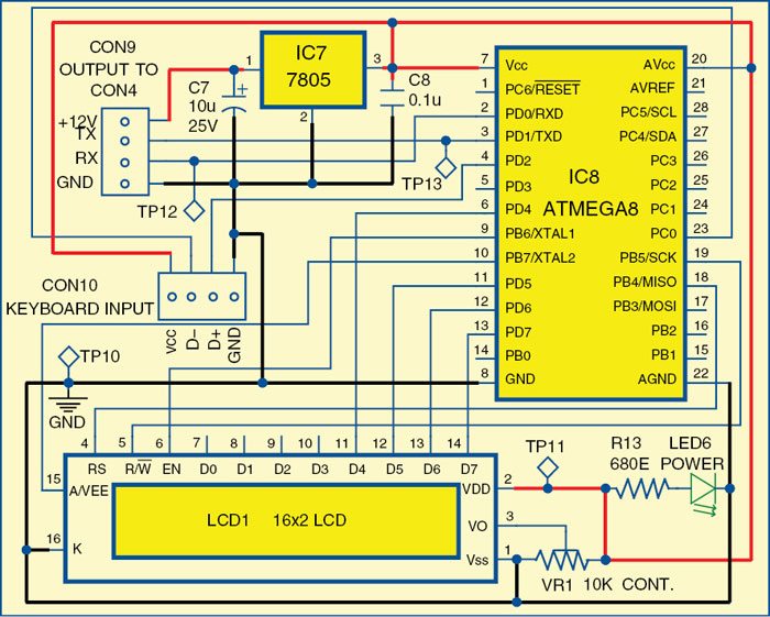
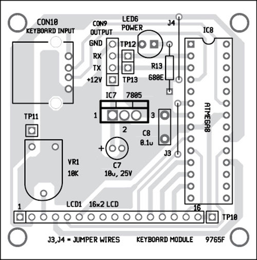
The keyboad interface module circuit is shown in Fig. 6. This module includes an ATmega8 microcontroller (IC8), keyboard input, 7805 regulator (IC7), 16×2 LCD (JHD162A) and a few other components. The input given from the keyboard is displayed on the LCD, and is simultaneously transmitted to the main module through connector CON9.
This module is basically for doing various settings like date and time, testing of each module and turning off the system using a specific command. It thus helps to set the system to correct values and operating parameters. This module is not us ed during normal operation and may therefore be kept disconnected.
A 16×2 LCD can display 16 characters per line and there are two such lines.
Software program
The program for the microcontroller is written in C language and compiled using gcc compiler. The compiler is used to convert C program into a hex file for burning into the flash memory of ATmega8 microcontroller.
In this project, the default internal oscillator is used for ATmega8 operation. The complete program is a combination of different functions. There are four main programs for this project: main_m.c, touchpannel.c, rlmod.c and lcdkbd.c.
The program starts with the main function that is used to configure the various ports of ATmega8 microcontroller as input/output and initialise UART module, and it calls UART_init() function to initialise to 4800bps and enable reception. The main function also enables the power-on relay used in the project to provide supply to the other sections.
[stextbox id=”grey”]
devswit() is used for switching between different devices connected in the system.
shut_down() is used to shut-down the complete system in shut-down mode and configure it in standby mode.
device_on() is used to switch on/off the corresponding relay for different appliances.
testm() is used to test system time configuration when powered on.
time_set() is used to set RTC time and date.
d_fnc( uint8_t l) is used to select various modes of operation of the system.
readm() is used for module name verification.
All functions related to LCD operation are included in lcd.h header file.
[/stextbox]
Construction and testing
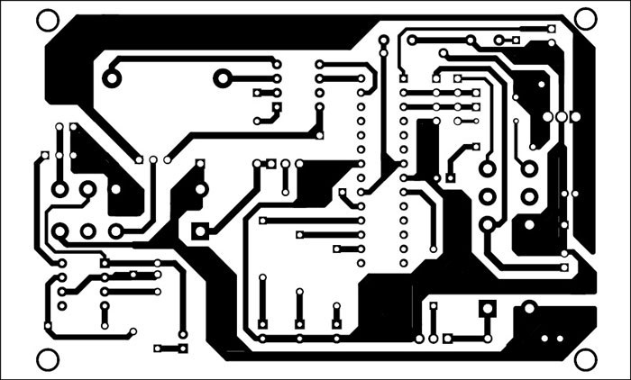
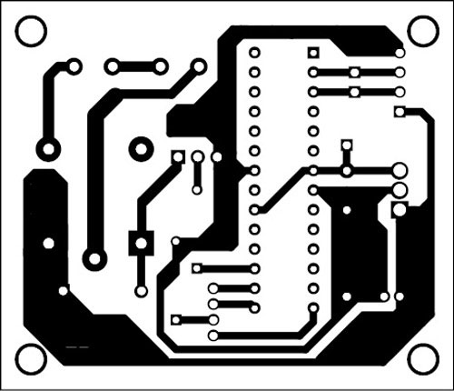
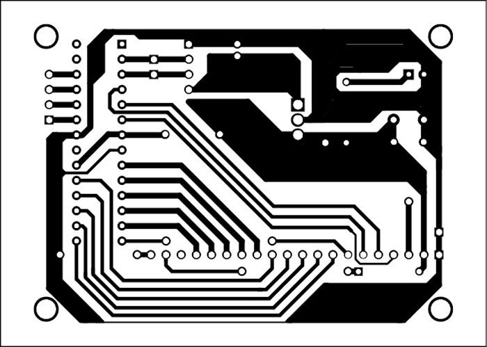
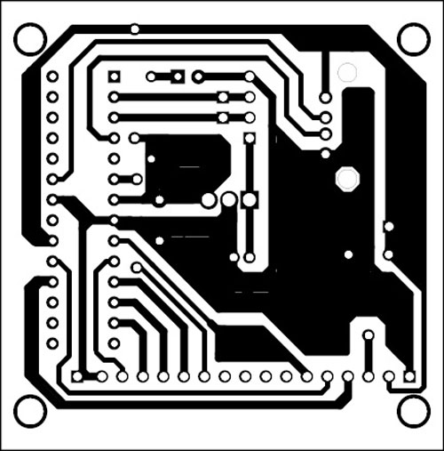
A single side PCBs for the four modules are shown in Figs 7, 9, 11 and 13, while their respective component layouts are shown in Figs 8, 10, 12 and 14.
Before using any SMPS power supply, you need to check ATX specifications, key mechanical dimensions, mounting points, I/O panels, power and connector interfaces. You also need to check SMPS connector pin details properly before connecting to the circuit.
There are 20-pin, 6-pin and 4-pin output connectors available on SMPS for various sections in the CPU. Wires are normally colour-coded; yellow is 12V, red is 5V, orange is 3.3V, black is ground and green is for PS_on (power on). You need to identify these wires, connect to suitable connectors for use in this circuit. Green wire should be connected to ground through power switch (S1) on the front panel of the CPU.
When AC supply is available on SMPS, it activates the +5VSB power supply on the main module, and the system goes to standby mode. As soon as the power switch (PS_on) is pressed, the main module becomes active and power-hold relay RL2 is energised, thus holding the supply while the program checks various statuses.
Download PCB and component layout PDFs: click here
Download Source code: click here
On completion of status checks, the system LED8 (RGB) will indicate the status of the load.
At this stage, unlock the touch-control panel by pressing Unlock, select the load or appliance you want to operate. Touch On or Off to switch on or switch off the load.
To change settings using the keyboard module, disconnect the touch-control module from CON4 and connect the keyboard module to it. Connect a PS/2 type keyboard to CON10 using a PS/2-to-USB converter. You will see various setting options on the LCD.
Testing of individual modules can be done by selecting the module and then the test mode. You can select the command from the command mode. Upon registering of the command, the system tests all devices’ on/off status indicators (RGB LEDs) and their corresponding relays.
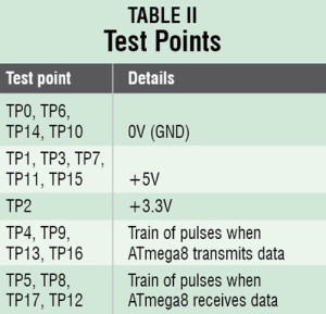
For troubleshooting, first check the voltages at various test points mentioned in Table II. Reset switch S2, which is connected on the front panel of the CPU, can be used during troubleshooting. On pressing switch S2, RL1 and RL2 are de-energised, and hence system goes to standby mode.
The article was originally published in December 2015 and has been updated recently.


code please
We have updated the source code. Please check.
home automation programming using touchscreen in 8051 controller
programme for micro controller
Kindly elaborate your query.
Simple learning, easy to understanding, Thanks a lot..
You are most welcome.
Nice job and a very good post friend. Thanks for this great article.
Thank you for your feedback.