


Construction and testing the audio visual alarm circuit
An actual-size, single-side PCB for the car-reversing audio visual alarm circuit is shown in Fig. 3 and its component layout in Fig. 4.
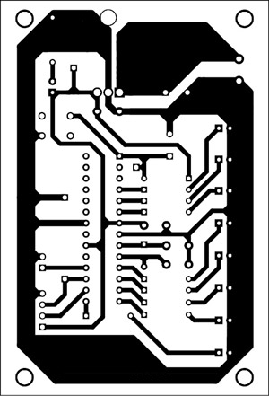

Download the PCB layout & component layout PDFs: click here
Download source code: click here
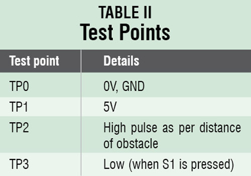
 Assemble the circuit on the recommended PCB to minimize assembly errors. Double-check for any overlooked error. Use proper IC base for the microcontroller. To test the circuit for proper functioning, verify correct 5V supply for the circuit at TP1 with respect to TP0.

For initial testing, just switch on the circuit and move an object in front of the sensor module. When distance between sensor and object is about 200cm, LED1 would glow. When the distance is about 25cm only, all the LEDs (LED1 through LED8) would glow and the buzzer will start giving a continuous beep sound.
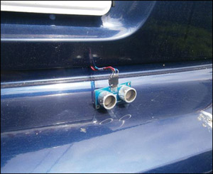
You can install the sensor module at the rear bumper of your car, as shown in Fig. 5. The LEDs (LED1 through LED8) and buzzer can be placed near the dashboard. The circuit should get switched on as soon as you place your car in reverse gear. As your car approaches an obstacle, more and more LEDs would start glowing. The audio visual alarm will give a continuous beep sound when distance between your car and the obstacle becomes 25cm or less.
The author is a B.Tech (electronics and communication). His interests include working with microprocessors and microcontrollers
